Capacitor and Reactor Matching for Detuned Banks
Capacitor reactor matching in a detuned bank means selecting the capacitor capacitance, reactor inductance, voltage rating, current capability and frequency as one coordinated branch. Matching only the nameplate kvar or the mounting size is insufficient. A replacement capacitor with the same kvar at a different rated voltage can have different capacitance, changing the branch’s detuning and operating stress. Start with the approved assembly data, confirm what each rating represents, and ask the supplier to verify the complete combination for the measured harmonic environment and enclosure conditions.
This guide addresses low-voltage detuned capacitor stages. It explains the checks needed for procurement and replacement, not a universal recipe for a tuned harmonic filter. For the system-level purpose, see why reactors are used in capacitor banks.
Begin with the branch rather than individual catalogues
A detuned stage contains a capacitor and series reactor, but the final output and loading belong to the assembled branch. The reactor changes impedance at both fundamental and harmonic frequencies. Its presence also changes the voltage across the capacitor. Therefore, standalone capacitor data cannot be used as the complete stage specification without accounting for the reactor.
Obtain the assembly drawing, nominal system voltage, frequency, connection, delivered stage output and approved part numbers. Identify whether the capacity stated in the quotation refers to the capacitor at its own rated voltage or the bank’s net output at the system voltage. Those values are not necessarily identical. Ask for clarification before comparing apparently equivalent offers.
For an existing installation, preserve the original reactor and capacitor identification even if the original supplier is no longer available. Photograph labels and connections during safe isolation, record the actual component arrangement and collect earlier test information. A bill of materials without the electrical relationships may not be enough to specify a replacement.
Capacitance depends on rated voltage as well as kvar
For a three-phase capacitor assembly expressed with equivalent per-phase delta capacitance C, the ideal reactive power is Qc = 3 × 2πf × C × U², where U is line-to-line voltage. Use consistent units: Q in var, frequency in hertz, capacitance in farads and voltage in volts. Other connection arrangements require the corresponding phase-voltage relationship; do not reuse the delta expression indiscriminately.
Consider an illustrative 25 kvar capacitor rated at 440 V and 50 Hz. The ideal equivalent delta capacitance per phase is about 137 microfarads. A 25 kvar capacitor rated at 480 V at the same frequency has an equivalent value of about 115 microfarads. These are arithmetic examples, not CNBYG catalogue specifications. Equal kvar on the two labels does not mean equal capacitance.
At a lower operating voltage, a capacitor’s standalone reactive output changes approximately with voltage squared in the ideal fundamental-frequency model. A detuned branch additionally needs the reactor effect included. This is why ordering a replacement by “same kvar, higher voltage” can alter the stage rather than simply improve its voltage margin.
Understand the detuning relationship
For an ideal series reactor-capacitor branch, define the fundamental-frequency detuning ratio p = XL/XC. With XL = 2πfL and XC = 1/(2πfC), p = (2πf)²LC. The corresponding ideal series-resonant frequency is fr = f/√p. In this expression p is a decimal ratio, so 7% is entered as 0.07, not 7.
A delta-connected bank must be converted to a consistent phase-equivalent model before pairing its capacitance with a line-connected reactor. Do not insert per-phase delta capacitance into a line-reactor calculation without that conversion. These equations describe the nominal relationship. Real assemblies include losses, tolerances, temperature effects and system interactions. Do not select a detuning percentage solely because it appears frequently in catalogues. The appropriate arrangement depends on the harmonic spectrum and network study. Detuned-reactor calculation covers the basic calculation, while project acceptance requires the manufacturer’s complete assembly data.
The underlying resonance principle is explained in the OpenStax series-resonance chapter. It is background theory, not proof that a particular industrial bank is free of resonance risks under every stage combination.
Make a matching worksheet before ordering
| Mục | Information to obtain | Tại sao điều đó quan trọng |
|---|---|---|
| System voltage and frequency | Actual nominal values and relevant operating range | Establishes fundamental impedance and voltage duty |
| Net stage output | Delivered kvar of the complete branch at stated voltage | Prevents confusion with standalone capacitor nameplate output |
| Capacitor arrangement | Capacitance, rated voltage, connection and number of units | Determines branch capacitance and replacement equivalence |
| Reactor data | Inductance, tolerance, detuning ratio and rated duty | Establishes the intended branch response |
| Harmonic environment | Voltage and current spectra with operating states | Supports harmonic-current and resonance assessment |
| Thermal conditions | Enclosure ambient, airflow and duty cycle | Establishes installation suitability |
| Protection and switching | Sensor contacts, switching device and discharge requirements | Supports safe integration and operation |
Use the worksheet as a procurement record. Leaving a field blank should trigger clarification, not an assumption that all suppliers use the same convention. The official IEC 60831-1 publication addresses low-voltage self-healing shunt capacitors; IEC 60076-6 addresses reactor categories and testing. Confirm the contractual applicability and evidence for the offered assembly.
Check capacitor voltage in the assembled branch
The reactor and capacitor voltages in a series AC branch oppose each other in the ideal reactive model, so the capacitor voltage can exceed the supply voltage. For the ideal fundamental-frequency case below series resonance, Uc = U/(1 − p). This relationship is a useful explanation of the voltage increase, but it excludes harmonics and tolerances.
For an illustrative 400 V supply and p = 0.07, the ideal value is approximately 430 V across the capacitor equivalent branch. It does not establish that a 440 V product is suitable, because actual duty includes voltage variation, harmonic components and the manufacturer’s rating rules. Obtain the approved capacitor voltage rating for the complete bank.
Do not solve repeated capacitor failures by raising the voltage rating while keeping every other nameplate value unchanged. Confirm capacitance and stage output simultaneously. See capacitor voltage-rating selection for the selection inputs, and retain the supplier’s matched-combination confirmation in the project record.
Reactor current and thermal duty need separate verification
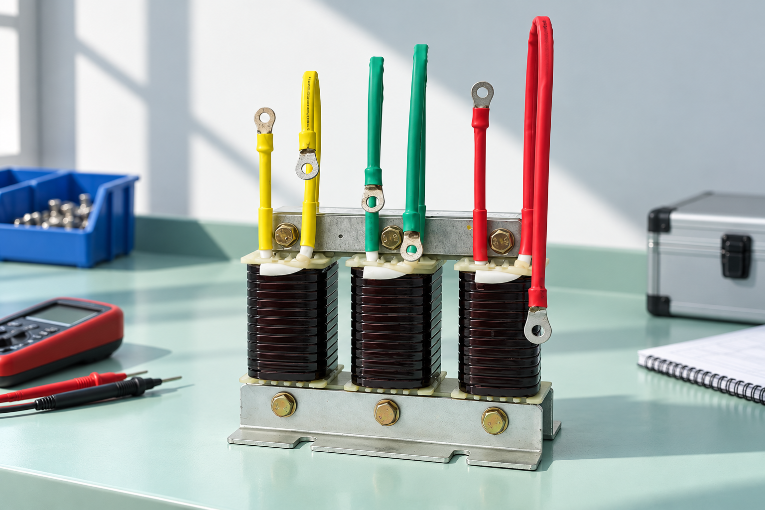
The reactor must carry the branch current and withstand the relevant harmonic duty. A match established at fundamental frequency alone may be insufficient when the plant has substantial nonlinear loading. Ask for the permitted current spectrum or the manufacturer’s selection assumptions, not merely a generic nominal-current label.
Review inductance tolerance and any specified saturation behavior together with thermal capability. Insulation class alone is not a complete loading specification. The allowed winding rise, ambient assumptions, mounting and cooling requirements must suit the panel. An electrically correct branch installed in an inadequately ventilated enclosure can still deteriorate.
Protection integration is part of matching. Identify thermal sensor contacts, wiring requirements, trip behavior and reset policy. A replacement reactor with a different sensor arrangement may require an approved control change. Do not leave the sensor unused just because the winding insulation class appears high enough.
Handle replacement capacitance measurements correctly
A measured capacitance value should be interpreted using the isolated arrangement, instrument method and manufacturer tolerance. Parallel units, delta connections and remaining discharge components can affect an in-circuit reading. Follow the prescribed safe isolation and measurement procedure rather than accepting a convenient value from an assembled stage.
Compare phases and the service history. A changed value may indicate deterioration, an incorrect replacement, a measurement problem or a difference between nameplate convention and the assumed calculation. Record which terminals were measured and whether units were separated. This information is essential when the supplier reviews apparent mismatch.
For a bank that has progressively lost capacity, investigate the cause before installing new capacitors. Capacitor capacitance-loss causes explains why a replacement-only approach can leave the original stress mechanism unresolved. Keep failed-unit data alongside the approved replacement selection.
Common matching errors during maintenance
One frequent error is combining a spare reactor with a spare capacitor because their kvar descriptions look similar. Reactor catalogues may express ratings in terms of an intended capacitor stage, while capacitor catalogues express standalone output at a rated voltage. The labels can therefore refer to different electrical quantities.
Another error is changing the number of parallel capacitor units without revisiting the reactor. This changes equivalent capacitance and may shift the detuning relationship. Replacing only one unit with a different capacitance can also create phase or branch differences. The whole arrangement needs to remain within the approved design.
Avoid copying a 50 Hz combination into a 60 Hz application. Both reactance values depend on frequency, and the assembled relationship must be checked. Likewise, do not assume a bank designed for one bus voltage can be transferred to another voltage simply by changing the controller target.
Verify the installed result under controlled conditions
Commission the stage using the approved sequence, instruments and qualified-person procedure. Record bus voltage, phase currents, relevant harmonic components, capacitor and reactor identification, temperature observations and controller operation. Compare the assembled output with the design definition rather than relying only on whether a contactor closes.
Do not bypass a thermal trip or reconnect a capacitor before its specified interval to accelerate testing. Stored energy must be addressed using the plant’s procedure. The initial verification should include the protection and switching sequence as well as the electrical measurements. Then repeat the relevant measurements during representative production states.
For CNBYG CKSG reactors, provide capacitor capacitance and arrangement together with the system and harmonic data. A documented matched proposal is more useful than requesting an isolated reactor by kvar alone. This article does not substitute for confirmation of the offered part numbers.
Further learning
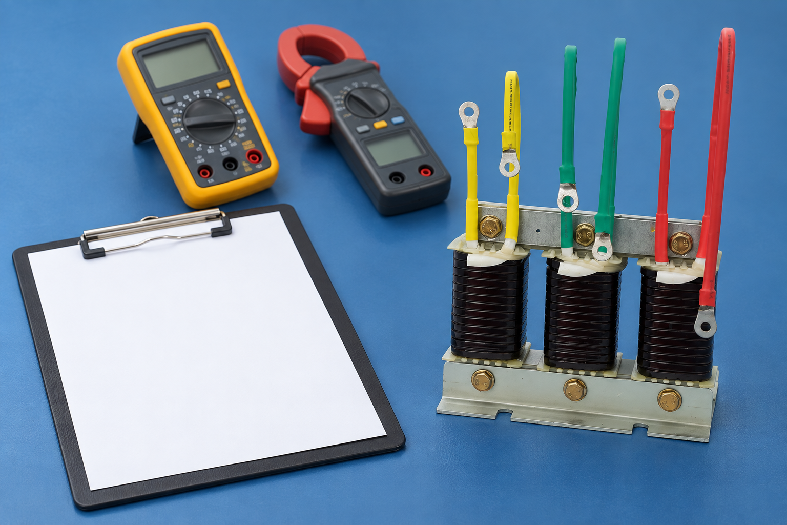
The inductor lesson explains magnetic energy storage and reactance. Use it alongside the capacitor-reactor equations here; it does not specify an industrial stage or authorize component substitution.
Các câu hỏi thường gặp
Can I replace a capacitor with the same kvar at a higher voltage?
Not without checking capacitance and the complete branch. Equal kvar at different rated voltages can mean different capacitance, changing detuning and net output.
Is a reactor’s stated kvar the same as capacitor nameplate kvar?
Not necessarily. Determine whether the rating describes an intended capacitor stage, standalone capacitor output or net branch output at the system voltage. Ask the supplier to state the convention.
Can a nominal detuning equation prove the bank is safe?
No. It establishes a basic relationship. Harmonics, source impedance, tolerances, thermal duty and protection require the complete assembly and installation assessment.
What should be sent to the supplier for matching?
Provide system voltage and frequency, required net stage output, capacitor capacitance and arrangement, reactor data, harmonic measurements, enclosure conditions and switching/protection requirements.