UPS Output / Load-Side APF
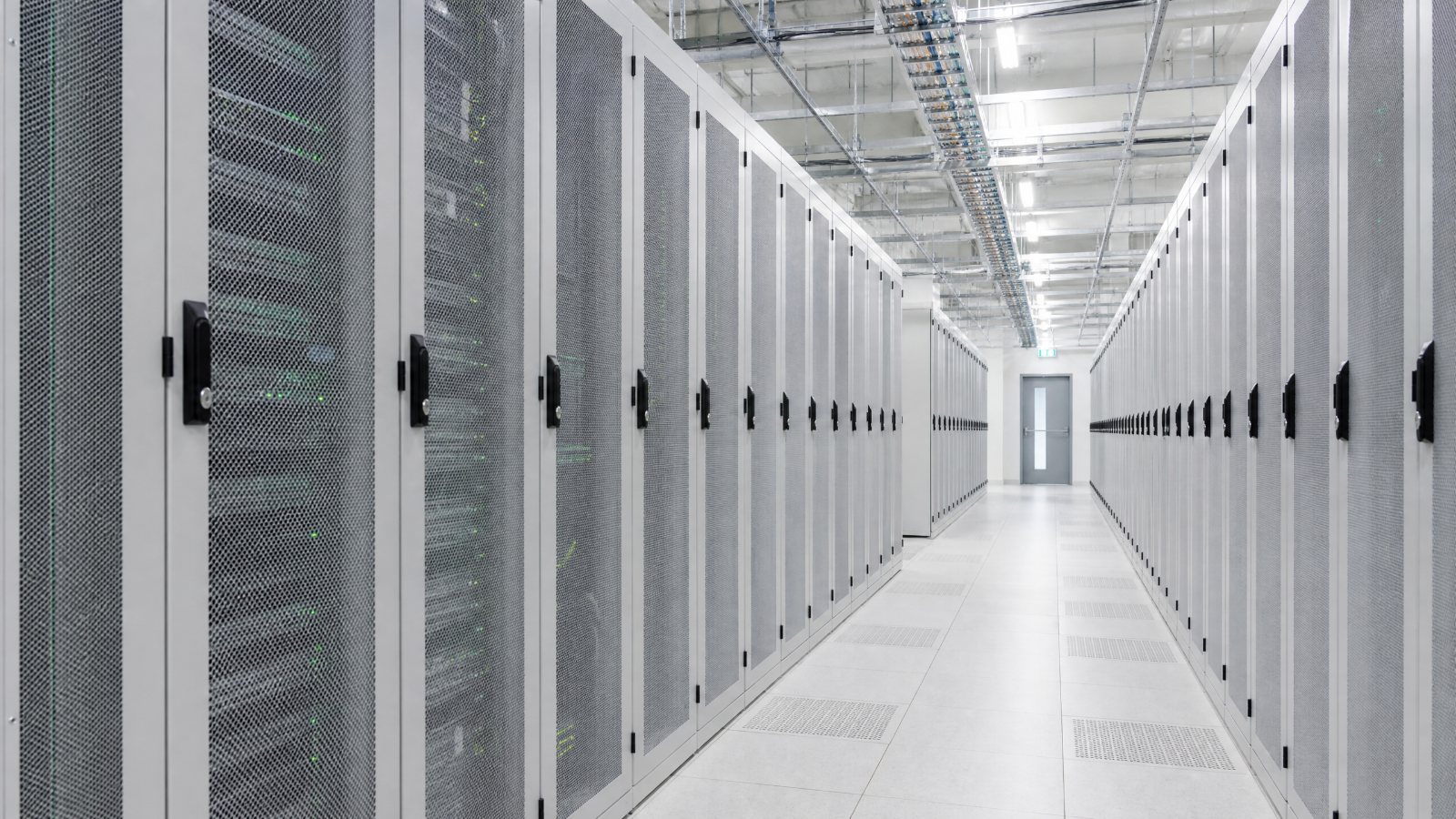
In a standard data-center distribution design, an APF usually sits upstream of the UPS and treats harmonics from the rectifier. Placing an APF on the UPS output, before the IT load, is a separate job. It does not replace the upstream treatment. It is a last check for residual harmonics that still reach the equipment after the UPS has stabilized the voltage.
This note is a branch of the Trung tâm dữ liệu solution. The upstream APF and SVG view stays on that page.
When the load side needs its own APF
Not every data center needs an APF after the UPS. The case is specific.
The UPS output is still distorted. Some UPS units, especially six-pulse rectifiers or units without an input filter, leave higher-order harmonics on the inverter output. Server power supplies and rack PDUs can also inject harmonics back onto that bus. When measured THDi at the UPS output stays above about 10% to 15%, a load-side APF has a job to do.
A filter inside the UPS is no longer helping. Some UPS units include a tuned branch, often around the 11th harmonic. With several UPS units in parallel, or with capacitive load downstream, that branch can become part of a resonance path and amplify one frequency. In that case the practical step is to take the internal branch out of service and let the APF cover the harmonic orders instead.
The IT load is unusually sensitive. Liquid-cooled servers and GPU clusters care more about voltage waveform and current harmonics, and their power-supply spectrum is not the same as a conventional server row. A modular APF at the row PDU or busway, close to those racks, keeps the distortion down where the equipment actually sits.
The neutral is overloaded. Triplen harmonics from switch-mode supplies add on the neutral. Neutral current can exceed a phase current. A three-wire APF cannot treat that zero-sequence current. The unit on the UPS output has to be a three-phase, four-wire APF with neutral compensation.
Where it goes, and how large it should be
Size the APF from a measurement at the point where it will be connected, not from a generic hall-wide number. Record at least 72 hours on the target UPS output: harmonic current through the 50th order, THDi, neutral current, imbalance, and how the load moves through the day. On a new build, a typical IT load downstream of a UPS is often in the 10% to 25% THDi range, and a switch-mode-heavy row can be higher. Recheck that estimate after commissioning.
The rated compensation current should cover the highest harmonic current you expect to treat, with about 20% to 30% in reserve. A simple check for a new design is load current times the typical THDi at that point, times 1.3. A 400 A UPS output bus at 25% THDi is about 100 A of harmonic current, and about 130 A after the margin, so a 150 A module, or a stack of smaller modules, is the right class of answer. If the APF sits at a row PDU, use that row’s current and THDi, not the whole UPS bus.
Data-center load arrives in stages, so a fixed cabinet ages badly. Modular APF, commonly 50 A, 100 A, or 150 A, in a rack or wall-mount form, can be stacked as the hall fills. On a UPS output bus that feeds a wide mix of loads, one modular cabinet beside the UPS output board is enough, sized for the whole downstream harmonic current. Where the distortion is local, in a dense GPU or liquid-cooled row, put a smaller module at the row PDU or busway and size it around 30% to 50% of that local load current. Leave one module slot empty so a later measurement can add capacity without replacing the cabinet.
Before the APF is connected, scan the circuit that includes the UPS, the downstream feeders, the row PDUs, and the server load. The APF is a new active impedance. If its control bandwidth lines up with a cable or capacitor resonance, it can create a problem it was meant to remove. That scan matters even more where power-factor capacitors or long cable runs are already in the room.
What has to be agreed with the UPS
Downstream of a UPS, the APF is a current source in parallel with a voltage source the UPS is actively controlling. The two suppliers need to confirm a few points before the order is placed.
The APF voltage window has to cover the UPS output, including the steady-state band and the short excursions. The response has to keep up with the load. A large GPU step can move faster than a casual specification suggests. A response inside 5 ms is the usual class of APF, but it still has to be checked against the actual load so the compensation does not lag or overshoot.
Look at the UPS waveform for notches. If they are obvious, a series reactor on the APF output is often needed, so the high-frequency edges do not stress the APF devices. The operating frequency has to match the UPS, 50 Hz or 60 Hz, including the allowed drift.
Resonance is the risk most often skipped. Prefer an APF that can add damping when a resonance starts, rather than one that only cancels harmonics after they are already large. If the site also has photovoltaic or storage on the same bus, give the APF supplier the scan and let them set the control from it.
Do not leave an internal UPS filter, a passive filter, and the APF all in service without checking how they share the job. If the internal branch is already part of a resonance, or it only duplicates the APF, open it and let the APF cover the 2nd through the 50th. Where capacitor banks remain, the APF should be able to trip those banks out when harmonics rise, instead of driving the resonance harder.
What changes after it is in service
On a UPS output bus that mainly feeds server power supplies, the usual aim is THDi at or below 5%, with a clear drop in neutral current. On one carrier IDC project the measured THDi fell from 47.1% to 4.5% after the APF was commissioned, across the 2nd to the 50th order. That is a project result, not a guarantee for every hall. The same reduction cuts extra loss in cables and transformers. The quieter benefit is fewer nuisance trips and a longer life for UPS and server power supplies, which usually matters more than the energy bill alone. Local savings still have to be calculated from the tariff, the load factor, and the hours.
How the work runs
Measure first. One to two weeks on the UPS output bus: THDi, harmonic current, neutral current, and the load curve, plus a scan for resonance.
Then size it. Choose a modular APF, and decide whether it must be four-wire, whether it needs a series reactor, and whether active damping is required.
Confirm the UPS limits: output voltage, load step, and waveform. Place the cabinet, put the current transformers upstream of the APF connection so they see the total current, and set the protection to match.
Commission against the same operating point used for the first measurement. If THDi, neutral current, or voltage distortion miss the target, check CT polarity, the control settings, and the damping.
After that, bring the APF into the DCIM: running state, compensation current, and the THDi trend, with an alarm when harmonics rise. The point of the branch is a control that stays visible, not a one-time correction.
Upstream treatment is a design choice. Load-side APF is the backup for what that design does not catch: residual harmonics, a filter inside the UPS that has started to resonate, and a neutral that is carrying too much. It earns its place only when the measurement comes first, the capacity has margin, the resonance is understood, and the UPS limits are confirmed.