


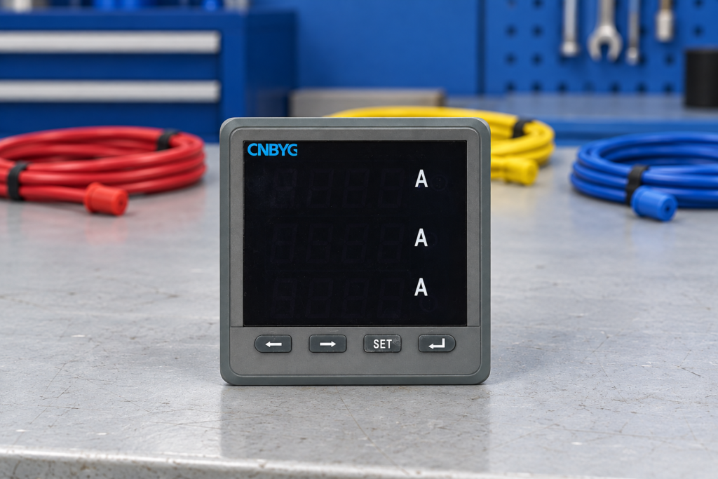
Power meter phase sequence describes the order in which the three voltage phases progress through their electrical cycle at the instrument’s measurement point. A reliable check distinguishes that voltage order from current-transformer polarity, voltage/current channel pairing and the meter’s selected wiring mode. Plausible voltage and current magnitudes alone cannot establish that power and power factor are correct. Begin with the approved drawing and exact meter instructions, retain the observed evidence, and use qualified personnel for electrical testing. This guide explains a commissioning review; it does not provide a universal terminal diagram or instructions for live rewiring.
Define the point where phase order matters
Identify the source, switchboard, feeder and meter location on a single-line diagram. Label the phases using the site’s approved convention. A report that simply says “sequence correct” is incomplete unless it identifies the test point, conductor labels and reference convention. Another feeder, a changed connection or a different test-lead order may produce a different observation.
Three-phase voltages are displaced in time. Their order is commonly described using labels such as ABC or ACB, but those labels depend on how the conductors and test channels are assigned. A phase-sequence indicator compares the signals connected to it; it does not independently establish the intended identity of every conductor in the building.
The engineering textbook LibreTexts lesson on polyphase motor design, explains phase rotation in polyphase circuits. That physical principle helps interpret the observation. It does not determine the correct wiring mode or terminal labels for a particular digital instrument.
Separate four questions that are easily confused
First, what is the voltage phase order at the measurement point? Second, does each current channel belong to the corresponding voltage phase? Third, is each CT’s orientation and secondary polarity correct? Fourth, does the configured measurement arrangement match the actual circuit? Each question requires its own evidence.
Changing a phase-sequence setting, when a model supports one, cannot be assumed to correct crossed current channels. Likewise, reversing a CT connection changes the sign relationship of that current but does not establish the supply’s voltage order. A technician who treats all four issues as one alarm can hide one fault while creating another.
Sử dụng hướng dẫn đấu dây đồng hồ đa chức năng for the overall installation review and the hướng dẫn lựa chọn CT for the current measurement chain. The present article focuses on interpreting phase-order and channel evidence, rather than repeating an installation checklist.
Confirm the meter can provide the claimed observation
Obtain the exact model and manual revision. Determine whether the instrument has a phase-sequence alarm, a phasor display, per-phase power values or only basic measured quantities. These capabilities vary. An exterior photograph or a product family name does not establish that the supplied unit supports a particular diagnostic function.
The Trang gia đình CNBYG BY194 can support an initial enquiry. Ask the supplier to confirm the ordered variant’s voltage channels, supported system topology and available diagnostic indications. Do not assume that every instrument in the family exposes the same display pages, alarm logic or communication registers.
If an instrument cannot provide the required evidence, use a suitable approved reference method. Record its identity, connection convention and limitations. A spreadsheet field filled by assumption is not equivalent to an observed phase-order result.

Review labels and drawings before testing
Trace the documented path from source phase labels to voltage sensing points, protective devices, terminal blocks and meter inputs. Separately trace the CT location and current channel assignment. Perform identification and continuity work only under the approved safe isolation procedure. Where drawings disagree with installed labels, resolve the discrepancy before accepting the measurements.
The Hướng dẫn an toàn điện HSE calls for secure isolation and checking that equipment is dead before work, and emphasizes competence for specialized inspection and testing. These principles apply even when the task sounds like a simple measurement check. The meter circuit can contain hazardous voltage, and CT circuits require their own controlled arrangements.
Do not open an energized CT secondary to investigate phase association. Follow the manufacturer’s instructions and the site’s approved shorting and testing procedure. This article intentionally provides no improvised switching sequence; the actual transformer, test facilities and installation determine the permitted method.
Read the voltage evidence without overinterpreting it
Where a suitable reference instrument is used under an approved procedure, record the connected conductor labels and indicated order. If the meter has a corresponding indication, compare the two using the same reference convention. A disagreement may involve the sensing path, labels, configuration, instrument capability or the observation method itself.
Check voltage magnitudes and missing-channel indications as well. A phase-order result obtained while a sensing input is absent or outside the instrument’s valid operating conditions may not support the intended conclusion. Use the exact instrument’s requirements to decide whether the observation is valid.
Do not interpret clockwise or counterclockwise symbols as universal physical labels. Their meaning follows the tester’s instructions and lead order. Also keep motor shaft direction separate: the direction of a particular machine depends on its wiring and mechanical arrangement, not solely on a meter’s screen symbol elsewhere on the network.
Examine current and power as a second layer
Once the voltage sensing arrangement is established, evaluate whether each current channel is paired with its corresponding voltage. A crossed current channel can leave voltage and current magnitudes looking reasonable while changing calculated active power, reactive power and power factor. Per-phase values or phasor information can help identify the inconsistency when the instrument supports them.
Use operating conditions that are understood and permitted by the test plan. A regenerative drive, local generation or a lightly loaded feeder can produce legitimate signs and angles that differ from a simple consuming-load assumption. Record the operating state instead of declaring every negative power value a wiring fault.
For direction-related interpretation, use the hướng dẫn năng lượng nhập khẩu và xuất khẩu. It explains why sign conventions and the measurement boundary must be documented. Phase-order review should not silently redefine import/export meaning to make a dashboard appear consistent.
Apply a diagnostic decision table
This table organizes observations; it is not an automatic fault diagnosis or a replacement for instrument instructions.
| Quan sát | Evidence to compare | Appropriate next investigation |
|---|---|---|
| Meter and reference show different voltage order | Lead labels, sensing drawing and configuration | Establish a shared convention and inspect the sensing path |
| Voltage order agrees but one phase power is unexpected | Current channel mapping, polarity and actual load direction | Investigate that channel without changing unrelated settings |
| Magnitudes look normal but total power disagrees | cURL Too many subrequests by single Worker invocation. To configure this limit, refer to https://developers.cloudflare.com/workers/wrangler/configuration/#limits | cURL Too many subrequests by single Worker invocation. To configure this limit, refer to https://developers.cloudflare.com/workers/wrangler/configuration/#limits |
| cURL Too many subrequests by single Worker invocation. To configure this limit, refer to https://developers.cloudflare.com/workers/wrangler/configuration/#limits | cURL Too many subrequests by single Worker invocation. To configure this limit, refer to https://developers.cloudflare.com/workers/wrangler/configuration/#limits | cURL Too many subrequests by single Worker invocation. To configure this limit, refer to https://developers.cloudflare.com/workers/wrangler/configuration/#limits |
| cURL Too many subrequests by single Worker invocation. To configure this limit, refer to https://developers.cloudflare.com/workers/wrangler/configuration/#limits | cURL Too many subrequests by single Worker invocation. To configure this limit, refer to https://developers.cloudflare.com/workers/wrangler/configuration/#limits | cURL Too many subrequests by single Worker invocation. To configure this limit, refer to https://developers.cloudflare.com/workers/wrangler/configuration/#limits |
| cURL Too many subrequests by single Worker invocation. To configure this limit, refer to https://developers.cloudflare.com/workers/wrangler/configuration/#limits | Before/after drawings, settings and intervention record | Compare the documented change before replacing equipment |
Define an acceptance record before correcting anything
Record the intended phase convention, instrument model, circuit topology, settings revision and required observations. Identify what constitutes acceptance for the application. The correct outcome may include agreement with a reference, correctly paired voltage/current channels, plausible power direction under known conditions and consistent communicated measurements.
Capture a pre-change record before an authorized correction. Include screenshots or exported observations, timestamps, operating load and the exact discrepancy. If the approved work changes wiring or settings, record what changed and why. Repeat the relevant checks afterward and retain both sets of results.
Do not issue a general “meter calibrated” conclusion from this process. A phase and channel review can establish configuration consistency under the tested conditions. It does not establish the instrument’s complete accuracy across all currents, power factors, frequencies or waveform distortions. Use a separate accuracy verification process for that question.
Avoid software corrections that conceal the cause
Some systems offer channel remapping or sign adjustment. Their availability does not establish that they are appropriate for a particular installation. Obtain the documented meaning of the feature, its effect on each measurement and the approval needed to use it. Confirm whether it changes only a display or also energy accumulation, alarms and communications.
An unexplained software reversal makes later troubleshooting harder. Another technician may follow the physical labels, replace an instrument, restore a settings backup and unknowingly reintroduce the fault. If a supported correction is authorized, make its purpose visible in the drawing, settings record and handover notes.
For a communication-only discrepancy, consult the Modbus commissioning guide. Keep the instrument’s electrical evidence and the supervisory decoding evidence available together. This prevents a tag formula from becoming an undocumented substitute for a correct measurement arrangement.
Specify useful diagnostic information when purchasing
Provide the intended topology, voltage sensing arrangement, CT arrangement and commissioning objectives with the enquiry. Ask which diagnostic values the exact variant exposes and how their meaning is documented. If remote support is important, request the corresponding register descriptions and a sample export format rather than assuming a local display page is remotely available.
Agree on the handover evidence before installation. A useful record includes the measurement boundary, phase labels, channel mapping, polarity convention, configured wiring mode, reference method and post-correction results. These details make future maintenance repeatable and help distinguish a new electrical problem from a changed configuration.
Học tập thêm
The neutral educational lesson below explains the time order of three-phase waveforms. It supports the concept; follow the approved installation and test procedure for any work on equipment.

Các câu hỏi thường gặp
Does a phase-sequence alarm prove that two supply phases are reversed?
Không. Kiểm tra định nghĩa của thiết bị, nhãn điện áp kết nối, điều kiện cảm biến và cấu hình. Xác định điểm đo thực tế và quy ước tham chiếu trước khi chẩn đoán nguồn cung cấp.
Liệu các giá trị điện áp và dòng điện có thể vẫn chính xác nhưng công suất lại bị sai không?
Có. Việc ghép nối điện áp/dòng điện không chính xác hoặc cực tính của biến dòng điện (CT) không đúng có thể ảnh hưởng đến công suất được tính toán, ngay cả khi các giá trị biên độ riêng lẻ có vẻ hợp lý. Hãy kiểm tra mối quan hệ giữa các kênh trong điều kiện vận hành đã được ghi nhận.
Tôi có nên hoán đổi dây dẫn CT để xóa bỏ cảnh báo thứ tự pha điện áp không?
Không thể đưa ra biện pháp khắc phục chung chỉ dựa trên cảnh báo này. Thứ tự điện áp và cực tính của biến dòng điện (CT) là hai vấn đề khác nhau. Nhân viên có chuyên môn phải tuân thủ quy trình chẩn đoán đã được phê duyệt và quy trình làm việc an toàn.
Do all BY194 instruments show a phase diagram?
Do not assume that they do. Confirm diagnostic functions for the exact ordered variant and its manual. A product-family photograph cannot establish a particular display or register capability.