VFD Harmonics in Industrial Plants: How to Measure and Select Mitigation
VFD harmonics in industrial plants should be investigated as a system issue, not assigned from a single drive nameplate. Variable-frequency-drive input rectifiers are nonlinear loads; they can inject harmonic current into the feeder and bus. The practical starting point is to measure both the affected distribution point and the point of common coupling (PCC), then select mitigation for the measured objective.
This guide separates drive-terminal troubleshooting, PCC planning, capacitor resonance risk, and active harmonic filter (AHF/APF) selection. It is intended for plant electrical engineers, panel builders, and EPC teams preparing an engineering review.
Contents
- Part 1: drive-input harmonic sources
- Part 2: measurement locations and records
- Part 3: mitigation-path comparison
- Part 4: capacitor-bank resonance boundary
- Part 5: APF capacity and location inputs
- Part 6: integration and commissioning
- Part 7: RFQ inputs and Fit Boundary
Part 1. Why do VFDs change an industrial plant’s harmonic profile?
VFDs regulate motor speed by rectifying incoming AC power, creating a DC bus, and synthesizing variable-frequency output. The input rectifier is nonlinear, so its current waveform is not a simple sine wave. A plant with a few lightly loaded drives may see a different result from a plant with many drives cycling pumps, fans, compressors, conveyors, or process motors together.
The relevant question is not “does a VFD make harmonics?” but “where does measured harmonic current create a planning or equipment problem?” Plant Engineering identifies reactors, multipulse arrangements, active-front-end drives, passive filters, and active filters as distinct mitigation paths. Their fit depends on load behavior, source strength, footprint, expansion, and the required measurement point.
| Plant symptom | Possible VFD-related contributor | First check |
|---|---|---|
| Transformer or bus heating | Harmonic current adds RMS heating | Trend current spectrum and temperature under comparable load |
| Nuisance breaker or relay action | Distorted current or a resonance condition | Check waveform, protection record, and capacitor status |
| High current THD at a drive feeder | Rectifier harmonic current | Compare feeder result with PCC measurement |
| Poor true power factor | Harmonic current and displacement effects | Record kW, kVA, PF, and spectrum together |
| Capacitor fuses operating | Harmonic amplification near resonance | Pause capacitor expansion and review detuning |
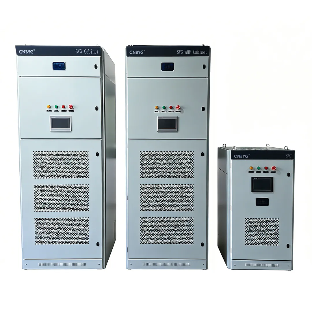
For general product context, see CNBYG’s Power Quality System page. It is not a substitute for a plant study.
Part 2. Where and how should VFD harmonics be measured?
IEEE 519 establishes steady-state harmonic-control design goals at the PCC. The PCC is a defined electrical interface, not automatically every drive input. A feeder measurement still matters because it finds the source and supports local mitigation, but it does not by itself prove the utility-facing condition.
Record a representative production window. Include normal throughput, the highest expected motor duty, changes in drive population, and switching events for any existing capacitor bank. A short measurement during light load can exaggerate current THD and conceal the current level that matters for a selection decision.
| Measurement point | Question it answers | Data to record |
|---|---|---|
| VFD feeder | Which drive group produces the current spectrum? | Phase current, individual orders, load state |
| MCC or distribution board | Are several drive groups aggregating? | THDi, kW, kVA, PF, unbalance, capacitor switching |
| Transformer secondary | Is distortion affecting the plant bus? | Voltage THD, current spectrum, temperature context |
| Defined PCC | What planning target applies at the source/load interface? | Voltage distortion, current demand, Isc/IL inputs |
Important: A clean-looking drive terminal does not establish PCC performance, and a high light-load THDi number is not by itself an APF capacity value. IEEE 519 describes distortion goals at the PCC and in steady-state conditions (IEEE 519-2022).
Part 3. Which findings call for reactors, AFE, passive filtering, or APF?
Mitigation is an engineering choice, not a product hierarchy. A line reactor can be appropriate at an individual drive when the local objective is input-current conditioning. A multipulse or active-front-end arrangement can be considered for a new-drive project. Passive filtering can be effective for a defined spectrum, while an APF is evaluated where varying harmonic current needs active compensation.
| Measured situation | Candidate path | Selection boundary |
|---|---|---|
| One or a few drives with local input concern | Line reactor or DC choke | Verify drive manufacturer guidance and feeder condition |
| New installation with defined drive topology | Multipulse or AFE drive | Compare cost, footprint, regeneration, and plant objective |
| Stable, known harmonic spectrum | Engineered passive filter | Check tuning, source changes, and resonance |
| Varying load and harmonic current at a reviewed bus | AHF / APF | Confirm topology, capacity, CT scheme, and target |
| Fast kvar swing without material harmonic current | SVG or other var solution | Do not substitute it for harmonic-current mitigation |
For a broader equipment workflow, read the active harmonic filter selection guide. Its framework should be applied to measured site data, not copied into an RFQ without the relevant waveform and demand records.
Part 4. Why do capacitor banks need a separate resonance check?
Capacitors do not create harmonics, but a capacitor bank and upstream inductance can form a parallel-resonance condition that amplifies harmonic current. Eaton’s VFD application note specifically warns that capacitor banks in distribution systems with six-pulse adjustable-frequency drives can result in undesirable resonant current, capacitor fuse operation, and higher bus-voltage distortion.
From the field: “when some motors are without VFD’s and some motors are with VFD’s, can we still use capacitors” is a recurring engineering question (Eng-Tips discussion). It is a valid reason to obtain a spectrum and capacitor-bank details before adding kvar; it is not technical proof for a particular plant.
Use the capacitor harmonic resonance guide when reviewing existing PFC equipment. A detuned bank, passive filter, or APF can each be relevant in different conditions; none should be selected from total motor kW alone.
Part 5. How should APF capacity and location be defined for multiple drives?
Define the APF at the point where compensation is needed. This can be a dedicated drive MCC, a process distribution board, or an upstream bus. The answer depends on whether the objective is to protect a local feeder, reduce aggregate plant harmonic current, or meet a PCC-based project target.
An APF capacity review should receive:
- A one-line diagram with transformer, feeder, capacitor, and drive locations.
- Time-aligned current trends and individual harmonic orders for representative operating modes.
- Maximum demand current and source short-circuit information where IEEE 519 assessment is required.
- Existing reactor, passive-filter, capacitor-bank, and protection details.
- CT installation point, direction, available cabinet space, thermal environment, and communication requirements.
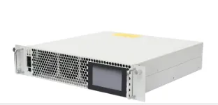
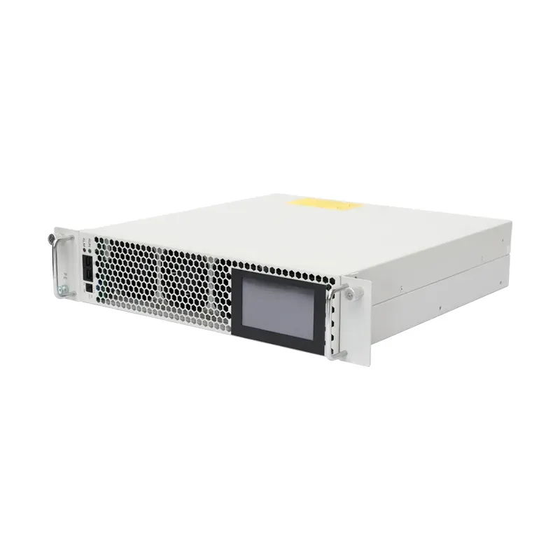
CNBYG positions AHF Active Harmonic Filter equipment for harmonic-current mitigation. Do not treat that positioning as a promise of a specific TDD, THD, savings, or equipment-protection result.
Part 6. What must be checked during integration and commissioning?
Commissioning must confirm that the equipment sees the intended current and that the before/after comparison uses the same operating condition. CT polarity, phase association, protection coordination, ventilation, and access for servicing should be checked before the first production test.
Use a practical commissioning sequence:
- Verify the one-line and CT location against the approved design.
- Record baseline voltage, current, spectrum, PF, and load state.
- Energize the mitigation equipment and verify stable control under normal load.
- Repeat measurements during the same drive duty and capacitor-switching condition.
- Compare the relevant bus and PCC values, not unrelated meter screenshots.
- Document alarms, communication mapping, and expansion constraints.
Part 7. What should an industrial VFD-harmonic RFQ include, and when is CNBYG not a fit?
| Buyer should provide | Why it matters | Common mistake |
|---|---|---|
| One-line diagram | Defines source, load, PCC, and candidate location | Supplying only motor horsepower |
| Drive inventory and duty profile | Shows aggregation and operating modes | Counting installed drives but not simultaneous operation |
| Meter trends and spectrum | Defines harmonic current by order and time | Sending one no-load THD screenshot |
| Transformer and utility fault data | Supports PCC and source-strength review | Omitting upstream source information |
| Existing capacitor/reactor data | Identifies resonance and retrofit risk | Treating PFC equipment as unrelated |
| CT/protection/space constraints | Determines installability | Leaving field integration unspecified |
Fit Boundary: This article fits industrial plants with drive-related harmonic concerns and a measurable distribution system. It does not replace utility coordination, protection engineering, drive manufacturer instructions, capacitor-bank design, or a model-specific performance guarantee. Share the data package through the CNBYG contact page when an AHF/APF review is required.
FAQ
What harmonics do VFDs produce?
Many common drive rectifier arrangements introduce characteristic harmonic current orders. Measure the actual spectrum because drive type, loading, transformer impedance, and other nonlinear loads change what appears at a bus.
Where should VFD harmonics be measured?
Measure at the affected feeder for diagnosis and at the defined PCC when the project includes PCC-based harmonic planning.
Do all VFD systems need an APF?
No. The mitigation method follows the measured objective, load variability, source condition, topology, and project target.
Can capacitor banks be used with VFDs?
They can require special engineering because capacitors can amplify harmonic current under a parallel-resonance condition. Review spectrum and detuning first.
Are line reactors enough for harmonic mitigation?
They can be useful for a local drive input, but they do not automatically solve an aggregate plant or PCC harmonic objective.
What is the difference between THDi and TDD?
Current THDi references instantaneous fundamental current. TDD references maximum demand load current and is used for IEEE 519 current-distortion assessment at the PCC.
How should an APF be sized for multiple VFDs?
Use representative harmonic-current trends, simultaneous operating load, spectrum, source information, and the required measurement point—not summed motor nameplate kW.
Does IEEE 519 apply at every VFD?
No. IEEE 519 establishes steady-state design goals at the defined PCC. Local feeder measurements remain useful for diagnosis and equipment location.