SVG Installation Requirements for Low-Voltage Switchboards
SVG Installation Requirements for Low-Voltage Switchboards
SVG installation requirements for low-voltage switchboards cover more than mounting a white enclosure beside a panel. The design must coordinate electrical rating, protection, CT location, conductor routing, ventilation, working space, enclosure protection, earthing, communications and commissioning. Begin with the one-line diagram and the selected model’s dimension and wiring drawings. Then assign responsibility for the completed switchboard assembly and acceptance test. A product photograph cannot establish the required clearances or verify compatibility with an existing board.
Define the connection before choosing the location
Identify the bus, feeder or load side where the SVG will connect. Record nominal voltage, frequency, phase/wire system, prospective fault level, grounding method, existing protection and the measured reactive-power duty. Note whether the SVG shares a cabinet with breakers, capacitor stages, reactors or active filters. The SVG product page is a starting point for product context; the selected model drawing controls the installation.
Place the CTs so the controller sees the intended load boundary. A CT on the wrong side of a transformer or parallel feeder can make a correctly wired SVG regulate the wrong quantity. Show CT ratio, polarity, phase order, cable route and terminal numbering on the approved diagram. Keep measurement circuits separate from power conductors where the design requires it.
Installation checklist table
| Area | Requirement to verify | Evidence before energization |
|---|---|---|
| Electrical rating | Voltage, frequency, phase/wire arrangement, current/kvar capability and ambient limits match the project | Approved datasheet, one-line and model number |
| Protection | Breaker/fuse, short-circuit rating, coordination, isolation and protective conductor are defined | Protection study and as-built settings |
| CT and control wiring | Ratio, location, polarity, phase order, terminal identification and communication path are correct | Wiring schedule, continuity/polarity record and settings backup |
| Mechanical support | Wall/frame, rails, mounting hardware, mass and removal path are adequate | Dimension drawing, fastening record and access review |
| Cooling | Airflow, heat rejection, ambient, filter pressure drop and neighboring heat sources are acceptable | Thermal calculation and site inspection |
| Enclosure/assembly | Ingress protection, cable entries, barriers, segregation and assembly verification are suitable | Assembly documentation and inspection checklist |
| Commissioning | Safe isolation, startup sequence, representative load cases and acceptance limits are documented | Approved test procedure and signed records |
Use the table as a preflight, not as a substitute for the manufacturer’s instructions or local electrical rules.
Mechanical placement and working space
Confirm the wall, frame or cabinet can support the complete SVG and allow safe removal. Preserve the model’s orientation and do not block vents, display access or terminal covers. Working space must account for the board door, adjacent equipment, cable bend radius and the tools needed for service. A location that technically fits the outline may still fail access or egress requirements.
For a rack unit, verify rail width, depth, support, connector access and module lifting. For a wall unit, verify anchors, backing, frame deflection and access above or below the enclosure. If the SVG is installed near a switchboard, define barriers and the isolation boundary so service on one piece does not expose personnel to another energized section.
The wall-mounted versus rack-mounted SVG guide provides a format comparison. Use the selected model’s drawings for the actual dimensions.
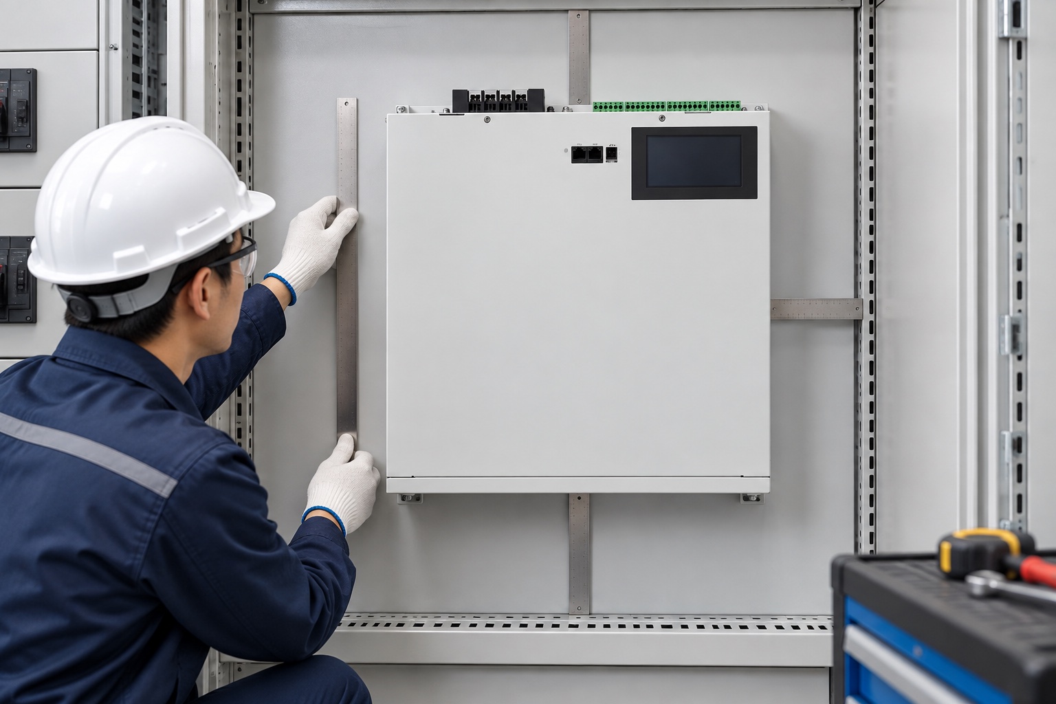
Image: illustrative installation-space review using the product-referenced wall SVG.
Electrical connection and protection
The SVG branch needs a defined connection method, protective device, cable or bus connection, isolation means and protective conductor. Confirm continuous current, short-circuit withstand, voltage drop and termination torque from the approved design. Do not choose a breaker only from the SVG’s nominal kvar. The upstream board, conductor, fault level and coordination study govern the protective arrangement.
Check whether the proposal includes a disconnect, branch protection, surge protection, control power, auxiliary supply and communication interface. Identify how the equipment behaves after a control-power loss, upstream trip or emergency stop. Record the expected state and reset procedure. If a capacitor bank or reactor shares the board, review switching transients and resonance interaction.
For a low-voltage assembly, IEC 61439-1 provides general rules for switchgear and controlgear assemblies. Apply the project-specified edition and local requirements. The standard does not give a universal SVG layout or replace the assembly manufacturer’s verification.
CT installation and phase identification
Mark the CT location on the one-line and wiring schedule. Confirm whether the controller measures source current, load current or a defined feeder aggregate. Check ratio, class, burden, polarity and phase labels. Keep the secondary circuit closed and follow the approved safe-work procedure. Never open a live CT secondary to “see what happens.”
At precommissioning, verify continuity, phase order and polarity using the approved instrument and method. Compare the measured direction with a known load state. A reversed CT can cause the SVG to increase rather than reduce the measured reactive current. If a four-wire function is required, identify the neutral or residual measurement path explicitly; do not assume the phase CT set covers it.
The SVG CT commissioning guide gives a practical evidence structure, while the selected manual controls the procedure.
Cooling, enclosure and environment
Power-electronic losses become heat inside the room or cabinet. Obtain model-specific heat rejection at the actual current and ambient condition. Maintain inlet/outlet clearances and avoid recirculating warm exhaust into another unit. For a cabinet, map airflow through filters, fans, module fronts and roof or door openings. A fan nameplate alone does not prove component temperature.
Account for dust, moisture, corrosive atmosphere, altitude and seasonal ambient. If the design requires an IP rating, IEC 60529 defines the degrees of protection provided by enclosures. Higher protection can reduce natural airflow, so confirm the cooling design after selecting the enclosure. Seal unused cable entries and preserve barriers and covers.

Image: illustrative low-voltage cabinet review; it does not show an energized connection.
Earthing, segregation and communication
Bond the enclosure and assembly protective conductor according to the approved design. Separate power, CT, control and communication wiring where required to limit noise and preserve measurement integrity. Confirm shield termination, network address, time synchronization and remote-stop behavior before startup. A communication alarm should not silently disable protection or leave a false “healthy” state.
Label the SVG, branch protection, isolation point, CT circuits and settings revision. Keep the as-built drawing, firmware, configuration export and test records together with the asset file. If the board will be expanded, document spare capacity and prohibited future connections.
Commissioning sequence
Before energization, inspect mechanical fastening, terminals, protective conductor, cable entries, CT circuits, barriers, covers, airflow path, control power and shipping restraints. Check the approved settings and firmware. Confirm the safe isolation procedure and emergency response. Energize under the manufacturer’s sequence, first confirming that no unexpected alarm, fan failure or thermal issue appears.
Record voltage, current, reactive power, power factor, ambient condition and SVG output with the unit disabled and enabled. Test representative inductive and capacitive states, phase or neutral behavior where applicable, alarms, limits and communication. Use the agreed measurement point and acceptance boundary. The SVG commissioning checklist can structure the records.
RFQ responsibility checklist
State who supplies the SVG, enclosure, breaker, CTs, cables, cabinet, drawings, assembly verification, installation labor, commissioning and performance report. Ask for dimension drawings, heat data, protection requirements, CT schedule, control wiring, communication protocol, spares, warranty and exclusions. Require a deviation list and a list of assumptions.
Do not accept “plug and play” wording as an installation method. A complete low-voltage switchboard design includes the surrounding equipment and the responsibility for proving it safe and functional.
Schedule a design hold point before procurement release. At that meeting, the switchboard integrator, SVG supplier, electrical contractor and site owner should review the one-line, CT boundary, protection, cabinet arrangement, airflow and shutdown plan together. Record unresolved interfaces as named actions with an owner and due date. This simple record prevents a late discovery that the supplied enclosure, breaker or CT kit does not match the board.
Keep a change log for any field modification. Moving a CT, drilling a cable entry, changing a fan, or changing a breaker setting can invalidate the original thermal or protection assumption. Update the drawing and repeat the affected inspection before energization. Do not rely on a verbal handover.
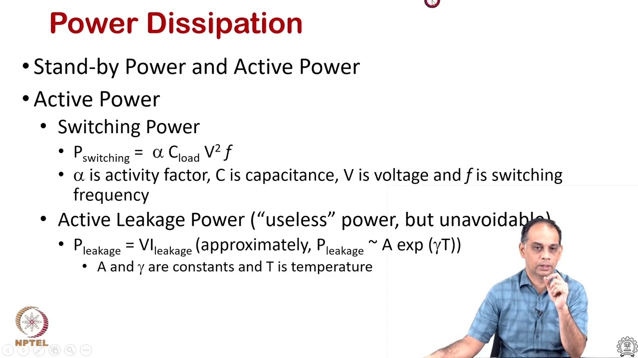
Neutral video: electronics cooling
NPTEL IIT Bombay’s cooling lecture explains general heat-flow concepts that help readers understand why airflow and heat rejection belong in the installation design. It is not a replacement for the model manual.
Frequently asked questions
Can I install an SVG inside any spare switchboard space?
No. Verify rating, protection, CT location, rails or wall support, airflow, clearances, assembly responsibility and service access for the exact model.
Does the SVG breaker size equal its kvar rating?
Not automatically. Use the approved current, voltage, cable, fault-level and coordination design. The upstream board and local rules also apply.
What should be checked before connecting CTs?
Check ratio, location, phase order, polarity, burden, continuity and the safe-work method. Keep CT secondary circuits closed and follow the approved procedure.
What documents should remain after commissioning?
Keep the as-built one-line, wiring schedule, settings and firmware record, CT data, protection settings, thermal inspection, test traces, alarms, acceptance result and responsible sign-off.
Installation outcome
An SVG is ready for service only when its electrical boundary, protection, CT measurement, mechanical support, cooling, enclosure, earthing and acceptance procedure agree. Complete those checks before energization and preserve the records for future maintenance.