When to Use ASVG Instead of Separate SVG and AHF Units
When to Use ASVG Instead of Separate SVG and AHF Units
Use an ASVG instead of separate SVG and AHF units when one coordinated converter can meet the plant’s reactive-current and harmonic-current objectives at the same electrical boundary, with acceptable capacity, redundancy, cooling and service risk. The decision is not based on footprint alone. It depends on the measured load spectrum, the voltage range, the required response, the control priority and what the site must continue doing during maintenance.
The CNBYG SVG and ASVG product page and the CNBYG AHF product page show the relevant product families. Ask for the exact model capability curve and installation drawing before treating a combined platform as a replacement for two independent systems.
Define the combined requirement
An ASVG-style combined solution is most defensible when reactive and harmonic problems occur at the same bus and are caused by the same operating states. Capture kW, kvar, power factor, phase current, voltage, THD and individual harmonic orders while the plant is at light load, normal production and peak production. Add generator transfers, capacitor steps and large VFD starts if they are part of normal operation.
The phrase “improve power quality” is not a specification. State the target power factor or reactive-current band, the harmonic orders and limits, the compensation point, response expectation, voltage range, ambient and what happens when the converter reaches its current limit.
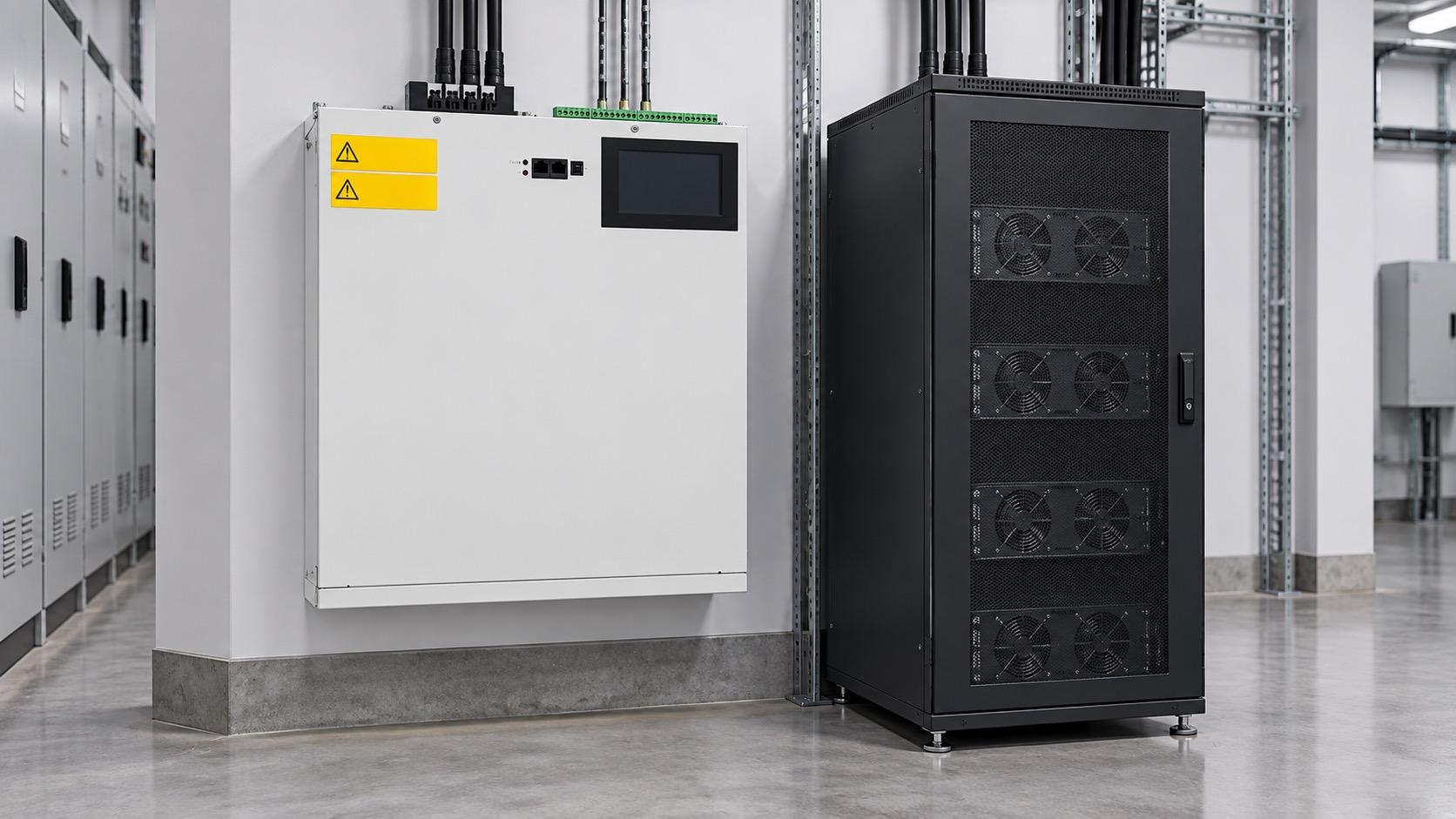
Decision table
Use the following screen before comparing quotations.
| Site condition | Combined ASVG is attractive when | Separate SVG and AHF are safer when |
|---|---|---|
| Electrical boundary | Both duties are measured at the same bus or incomer. | Reactive and harmonic sources are at different buses. |
| Load profile | Reactive and harmonic peaks occur together and are predictable. | One duty peaks when the other is quiet or changes independently. |
| Capacity | Simultaneous current and thermal capability has documented margin. | One combined current budget would be saturated frequently. |
| Availability | A planned common service window is acceptable. | One function must remain available while the other is serviced. |
| Cabinet and cooling | One coordinated enclosure fits with service and thermal clearance. | Independent cabinets improve airflow, bypass or physical separation. |
| Controls | Priority, fallback and communications are simple and approved. | Separate control ownership or redundancy is required. |
| Future changes | Load growth is known and within the combined capability curve. | Future expansion may require independent scaling or technologies. |
Check the current budget
Reactive kvar and harmonic RMS current should be calculated at the actual line voltage and operating state. Do not add nameplate values without understanding how the converter allocates current. Ask the supplier for the combined capability curve, minimum and maximum voltage, ambient derating, overload duration, priority logic and limit indication.
The SVG output-capacity guide explains why voltage changes the current needed for a given kvar. The same voltage and thermal conditions affect a combined unit’s harmonic duty. A unit that meets the reactive target at nominal voltage may have less harmonic headroom during an undervoltage event or a hot cabinet.
Choose a common measurement point
An ASVG is easier to coordinate when one CT schedule and one voltage reference describe both objectives. Verify CT ratio, polarity, phase assignment, location, burden and controller input range. Save the harmonic spectrum and the reactive-current sign convention. If an AHF was previously installed at a downstream feeder, moving the measurement point to the incomer can change the required current and the apparent result.
Compare the equipment display with an independent analyzer. A combined unit can report reactive success while the source still sees harmonics if the measurement boundaries differ. The SVG commissioning checklist provides a useful evidence structure for phase, CT and trace checks.
When combined architecture wins
Combined architecture can be a good fit when cabinet space is tight, the same feeder contains the nonlinear and reactive loads, and the plant benefits from one controller, one communication interface and one coordinated service plan. It can also simplify a new installation where the supplier can provide a tested platform with clear priority behavior.
Keep the benefits practical. A smaller footprint is not a benefit if the cabinet loses service clearance. One controller is not simpler if a network failure leaves the plant without a safe fallback. A common spare strategy is valuable only when the replacement module is approved for the exact hardware and firmware revision.
When separate units win
Separate SVG and AHF units are often preferable when the duties are physically separated, when one objective is critical during the other’s maintenance, or when the load growth path is uncertain. Independent ratings can avoid a combined current bottleneck and can make acceptance tests easier to interpret.
Separate equipment can also help when an AHF must target a particular nonlinear feeder while the SVG serves the main bus. The trade-off is more cabinet space, more CT and communication coordination, and potentially more maintenance points. Document those costs rather than assuming that independent means automatically better.
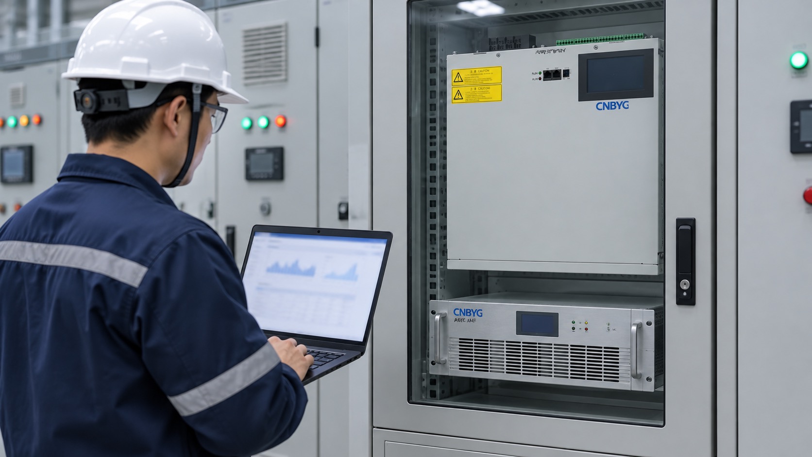
Application and service review
Check mounting, bus, breaker, cable, ventilation, heat rejection, access, isolation and bypass. Confirm that one product’s exhaust does not heat the other inlet. Decide whether both units can be isolated independently and whether the plant can operate at reduced production if one function is unavailable.
The wall-mounted versus rack-mounted SVG guide helps frame enclosure and service choices. Include the AHF’s filter, fan and control-board service needs in the same maintenance plan; an ASVG/AHF decision is an operating decision, not only a procurement comparison.
Selection workflow
- Measure reactive and harmonic conditions at the intended boundary.
- Separate normal, peak, light-load and generator-transfer cases.
- Define reactive target, harmonic orders, voltage range and response expectations.
- Request simultaneous-duty curves and current-priority behavior for combined solutions.
- Compare common and independent CT, protection, cooling, service and communication designs.
- Write acceptance cases for each objective and for current-limit fallback.
- Record assumptions, limitations, future growth and the chosen maintenance strategy.
Acceptance testing
Start with a dead inspection and measurement verification. Enable one objective at a time, then test the combined mode under representative load steps. Record voltage, current, kW, kvar, PF, THD, harmonic orders, output current, temperature, alarms and communication state. If a current limit is reached, record which objective was prioritized and whether the result is acceptable.
For general measurement method context, see IEC 61000-4-30 in the IEC catalogue. Use the model-specific manual for protection, isolation and commissioning limits.
Lifecycle and procurement checks
Review the combined platform over its full service life. A single enclosure can simplify spare holding and operator training, but it can also concentrate heat, control and communication dependencies. Request the expected fan and filter service intervals, firmware policy, replacement lead times, approved spare list and remote-support requirements. Confirm whether the supplier can provide separate traces for reactive and harmonic performance so future troubleshooting does not depend on one combined display value.
Ask the electrical contractor to price the complete installed scope: breaker, cable, CTs, voltage sensing, cabinet modifications, ventilation, lifting, testing, settings, training and documentation. A combined unit may save panel space while requiring more sophisticated CT routing or a different bus arrangement. Compare the installed cost and outage duration, not only the equipment line item.
Growth should be explicit. If a new VFD line or transformer is planned, state its expected kvar and harmonic spectrum and ask how much headroom remains after the expansion. If the platform supports parallel modules, require the current-sharing method, firmware compatibility and one-module fallback test. If it does not, do not present an empty cabinet slot as future capacity.
The owner should also decide who can change priorities. A plant controller, energy-management system or local technician may all have access to settings. Use role-based permissions where available, keep an approved baseline and record every change. During a communication outage, the fallback must preserve protection and a predictable operating mode.
These checks turn “when to use ASVG” into an engineering decision that remains valid after commissioning. They also make separate SVG and AHF equipment easier to compare because the same lifecycle assumptions are applied to both options.
Frequently asked questions
Is ASVG always cheaper than two separate units?
Not necessarily. Compare converter capacity, cabinet, CTs, protection, cooling, controls, spares, service windows and future expansion rather than only purchase price.
Can a combined unit be expanded later?
Only if the model family, controller, firmware, bus, cooling and current-sharing design explicitly support expansion. Empty cabinet space is not proof of compatibility.
Which priority should be used when current is limited?
Use the priority that protects the plant’s contractual and operational objective. Define it before commissioning and document the fallback behavior.
What is the most important quotation question?
Ask what reactive and harmonic current are guaranteed simultaneously at the minimum voltage, maximum ambient and worst normal load state.
Conclusion
Choose ASVG instead of separate SVG and AHF units when the electrical boundary, load profile, current budget, controls, cooling and service strategy genuinely support one coordinated platform. Choose separate units when independence, physical separation, redundancy or future scaling is more valuable. Measure first, define priority and require simultaneous-duty evidence.
Neutral video: active-filter background
The lecture below is neutral educational context for shunt active-filter operation, not a product recommendation.