Reactive Power Compensation for Cement Plants
Cement plant reactive power compensation should follow the measured active and reactive power profile of the production process, together with harmonic and supply-system evidence. Map large motors, variable-frequency drives, existing capacitor banks and the actual metering boundary before choosing fixed, stepped or dynamic compensation. A target power factor alone is not enough to size equipment. The selected arrangement must also behave acceptably during reduced production, mill changes, shutdown and permitted alternative supply configurations. Keep displacement power factor separate from distortion-related reductions in true power factor so that the proposed remedy addresses the measured cause.
Define the plant boundary and production states
Start with the verified distribution drawing. Identify the utility connection, transformers, major switchboards, large motors, drives, existing correction banks and relevant metering locations. Record which loads belong to the commercial metering boundary and which measurements are intended only for internal diagnosis. A local mill feeder and the utility interface answer different questions.
Then connect electrical records to production. Raw milling, kiln operation, fans, conveying, cement grinding and packaging may operate in different combinations. Use the actual plant arrangement rather than assuming every cement plant has the same process or motor list. Changes in production rate can change both active power and reactive demand; retain these changes in the operating log.
Note equipment already installed for compensation. Obtain its rating, connection voltage, switching arrangement, controller settings, reactor information and current condition from verified documentation. An old drawing is a starting point, not proof that every capacitor stage remains operational or that the bank is suitable for the present drive population.
Establish the quantity that needs correction
Record active power, reactive power, apparent power, voltage, current and the relevant power-factor definitions over representative operation. Confirm the meter’s method, phase connections and sign conventions. If instruments report different quantities, identify their definitions before combining them into one sizing spreadsheet.
Displacement power factor concerns the fundamental-frequency relationship between voltage and current. True power factor includes the overall relationship between active and apparent power and can also be affected by distorted waveforms. Adding ordinary capacitors does not automatically remove that distortion. A plant can have a good displacement factor and still need a separate harmonic investigation.
IEEE 1459-2025 provides definitions for electrical-power measurement under sinusoidal, nonsinusoidal, balanced and unbalanced conditions. Use a stated method and consistent quantities in the project report rather than treating every instrument’s PF label as interchangeable. Record the instrument and configuration with the exported data.
For process comparisons, align timestamps with the production log. A low power-factor interval during reduced active power should not be interpreted without its reactive demand and duration. Likewise, a billing-period value does not identify which feeder needs an engineering change. Separate the commercial objective from the electrical design evidence needed to meet it.
Build a production-state survey
Include representative higher output, reduced production, transitions between major loads and the normal shutdown arrangement. Capture sufficient duration to represent the operating cycle and the contractual measurement basis. Do not choose only the interval that produces the largest compensation requirement or the most favourable before-and-after result.
| Production or supply state | Evidence to retain | Compensation question |
|---|---|---|
| Major process loads operating | Time-aligned active and reactive power, voltage and bank status | What reactive demand remains with the actual production combination? |
| Raw or cement mill change | Feeder records, switching timestamps and process-state note | Is demand changing faster than the present arrangement can follow? |
| Reduced production | Reactive demand, active power and remaining fixed stages | Does the installation become overcompensated at light load? |
| Drive-heavy operation | Current spectrum, voltage distortion and displacement factor | Is poor true power factor partly a distortion problem? |
| Planned shutdown | Loads left energised and correction stages retained | Which compensation should remain enabled under the approved design? |
| Alternative supply configuration | Source details, permitted loads and correction-device position | Does the tested arrangement remain suitable on that source? |
This table gives a qualitative survey framework, not a universal rating or switching rule. Choose operating tests with the responsible plant engineers and preserve process interlocks. A recorded cement-factory investigation such as the Journal of Engineering and Sustainable Development study is useful background, but its site-specific results should not be copied as the rating or savings for another factory.
Use a first estimate with explicit limitations
For a balanced sinusoidal load at a stated active power, a common first estimate is Qc = P × (tan φ1 − tan φ2). P is active power in kW; Qc is the reactive correction estimate in kvar; φ1 and φ2 correspond to the initial and target displacement power factors. This calculation describes a chosen operating state, not the final hardware design for an entire variable production cycle.
For an illustrative example, take 500 kW at an initial displacement factor of 0.80 and a target of 0.95. The initial tangent is 0.75, and the target tangent is approximately 0.329. The estimated correction is about 500 × (0.75 − 0.329), or 211 kvar. These are invented teaching inputs, not measured cement-plant data or a recommended CNBYG equipment rating.
Repeat the assessment across the measured load range and retain reactive-power sign. The useful design input includes low-load conditions, not just the peak estimate. A fixed correction chosen for the peak may be excessive when large motors stop. Account for existing effective compensation rather than adding the whole calculated amount again.
Do not apply this simple expression as a substitute for a distorted-waveform assessment or assume that correcting fundamental reactive power will achieve any chosen true-power-factor target. The displacement and distortion power-factor logging guide supports separating these quantities in the survey.
Assess harmonics and capacitor interaction
Large drive populations warrant a harmonic-current and voltage-distortion assessment. Identify actual converter types and existing input components, and compare representative operating combinations. A generic claim that all drives have the same distortion is not an acceptable basis for compensation design.
Capacitor banks interact with the network impedance. Adding capacity, changing transformer configuration or introducing new drives can change that interaction. Review the relevant network study and equipment condition before selecting an ordinary bank, a detuned arrangement or a separate harmonic solution. A reactor percentage should follow a verified design and operating voltage, not a rule copied from a different plant.
The IEEE 519-2022 standard page describes harmonic control at the supply interface and its steady-state scope. Establish the applicable location and project criteria; an internal drive reading is not automatically a supply-interface compliance result. Keep transient disturbances and harmonic acceptance as separate parts of the investigation.
For a kiln-specific drive operating log, use the existing cement kiln VFD harmonics guide. That narrower feeder task complements the plant-wide reactive-power survey rather than duplicating it.
Compare fixed, stepped and dynamic correction
Fixed compensation may suit a sufficiently stable and properly coordinated task, but its suitability depends on what remains energised when the associated load changes. Verify the installation arrangement and switching coordination. Do not infer that a continuously operating process always has a constant reactive demand.
Stepped capacitor compensation can follow varying demand within the controller and switching arrangement’s verified capability. Stage size, timing, voltage suitability, discharge requirements and existing harmonic conditions matter. Frequent stage changes are a reason to inspect the demand profile and configuration, rather than merely increasing a delay or adding more stages.
Dynamic reactive-power equipment can be considered when the measured demand and required response support it. An SVG proposal should state the model’s verified functions, correction range, response, voltage suitability, thermal limits and connection arrangement. Reactive-power correction, unbalance correction and harmonic correction are separate capabilities that must not be assumed from a generic product name.
The CNBYG SVG product page provides a relevant enquiry starting point. Send the measured demand profile and engineering requirements for a model-specific assessment. The SVG sizing guide for dynamic loads supports the response and operating-range discussion.
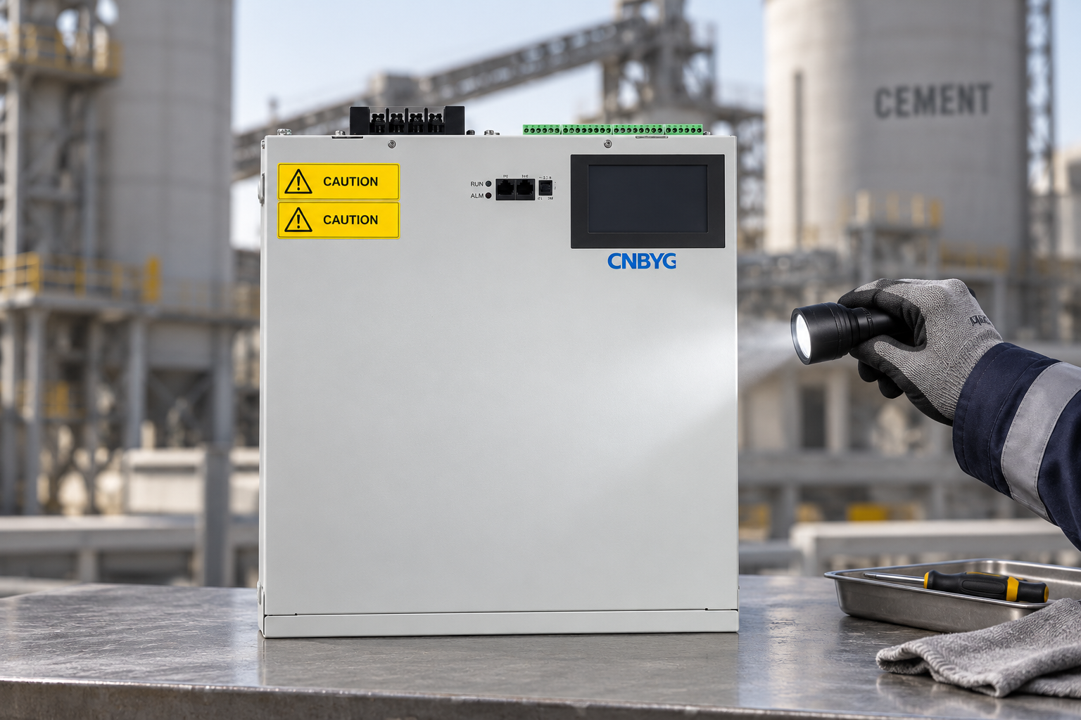
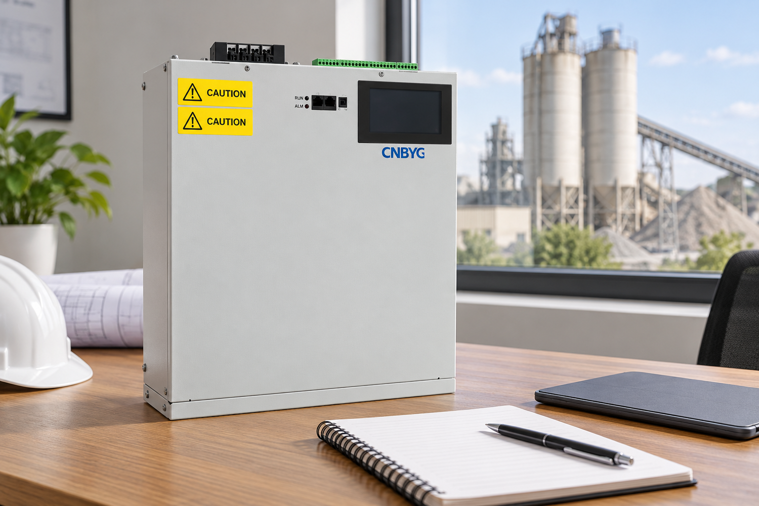
This product-reference illustration supports an enclosure and installation discussion. It does not certify a connection voltage, a correction capacity or suitability for a particular cement plant. Warning markings are simplified for illustration; use the actual equipment labels and documentation for installation and safety.
Plan the location and coordination
Compare compensation at a major load, a distribution board and the wider plant connection. Local correction and central correction can have different effects on feeder reactive current and on the measured utility-interface quantity. The design should identify the intended result at each location and prevent uncontrolled interaction between devices.
Verify current-sensor positions, phase association, existing controller behaviour and which loads fall inside each control boundary. Two devices responding to an unclear common signal can produce misleading or unstable behaviour. Record the approved settings and drawing before commissioning, with a clear responsibility for subsequent changes.
Environmental conditions also matter. Cement operations can involve dust and demanding maintenance access, but the actual enclosure conditions must be assessed rather than guessed from the industry label. Obtain model-specific installation and cooling requirements and include access, cleaning and inspection responsibilities in the maintenance plan.
Define acceptance before purchasing equipment
Agree the baseline and final production states, measurement positions, power definitions and relevant distortion criteria. Use consistent instrument settings and explain any changes in production or supply configuration. A higher measured power factor on a different production day does not independently establish the equipment’s benefit.
Compare active and reactive power profiles, power-factor quantities, voltage behaviour, distortion evidence and correction-device status. Check reduced-load and shutdown conditions as well as representative high output. Do not declare acceptance for an alternative source arrangement that was not tested or otherwise validated by the responsible engineer.
Where an economic assessment is requested, use the actual tariff, contract and measured billing quantities. Reactive-power correction does not guarantee an equivalent reduction in process energy consumption. Do not present hypothetical penalties or laboratory examples as the plant’s confirmed savings. Separate measured electrical improvement from the financial result.
Retain final drawings, instrument exports, settings, alarms and the accepted operating conditions. Review the compensation arrangement after major motor or drive changes. These records help future engineers understand the design basis and investigate a changed result without repeating unsupported assumptions.
Further learning: standards and monitoring
The NPTEL IIT Delhi lecture, Power Quality: Standards and Monitoring, provides general education relevant to measurement quantities and acceptance boundaries. It does not replace a plant survey or endorse a particular compensation product.

Watch Power Quality: Standards and Monitoring
Frequently asked questions
Can cement plant compensation be sized from transformer capacity alone?
No. Transformer capacity gives part of the system context, but the correction task depends on measured reactive demand, production states, existing equipment and network conditions. Use those records for engineering selection.
Will capacitor banks correct every low power-factor result?
No. Separate fundamental reactive demand from distortion-related reductions in true power factor. Ordinary capacitors are not a general harmonic-removal device, and network interaction requires assessment.
Is an SVG always preferable to stepped capacitors?
No. Compare the actual demand variation, required response, harmonic conditions, operating range and verified equipment capability. A stable task and a rapidly varying task may justify different arrangements.
What should the final enquiry include?
Include the verified single-line diagram, production-state P and Q records, power-factor definitions, harmonic evidence, existing bank details, supply configurations and acceptance criteria. Clearly identify any operating conditions not yet measured.