Power Quality for Microgrids: Measurement and Mitigation
Microgrid power quality must be assessed separately during grid-connected operation, island operation and transitions between them. Define the electrical boundary, source controls and load combinations before selecting measurement equipment or mitigation. Record voltage, frequency, waveform distortion, unbalance and relevant events with synchronized operating-state information. A solution that performs correctly while connected to a strong utility supply is not automatically suitable when the microgrid becomes an island. Active harmonic filters, reactive compensators and source controllers have different jobs; their compatibility and operating permissions must be established for the actual equipment and every approved mode.
Start with the boundary and operating modes
Mark the utility interface, internal buses, distributed sources, energy storage and critical loads on the verified single-line diagram. Identify which equipment controls voltage and frequency in each operating mode. The term microgrid describes a system arrangement; it does not prove that every connected inverter can establish an islanded supply.
List normal grid-connected operation, planned island operation, any permitted unplanned island response and reconnection. Include transitions only where they are part of the approved system design. Write down the sources and loads allowed in each mode, and identify operating combinations that have not yet been validated.
A review such as the IntechOpen chapter on renewable-energy microgrid power quality can provide background on the range of issues. Use the specific study and equipment documentation for project decisions rather than copying another microgrid’s controller, compensation rating or reported improvement.
Separate continuous conditions from events
Continuous or aggregated measurements can describe voltage magnitude, frequency, harmonics and unbalance during an operating interval. Event recordings describe disturbances such as voltage changes and interruptions. Both are useful, but an average value can hide a short event during a mode transition.
Define the question before choosing the record. If sensitive equipment trips during islanding, obtain synchronized event evidence and relevant controller logs. If the problem is sustained harmonic distortion in one load combination, retain the current spectrum and corresponding bus voltage. Do not prescribe a harmonic filter solely because a general power-quality alarm occurred.
Include the condition of the utility supply when connected. An upstream disturbance can enter the microgrid through its interface, while a local load or source can create an internal problem. Measurements on both sides of a defined boundary, where safely and appropriately arranged, can help distinguish the origin and propagation of an event.
Build an operating-state measurement matrix
| Operating state | Minimum context to retain | Question to resolve |
|---|---|---|
| Grid-connected, typical load | Utility condition, source dispatch and feeder measurements | What is the normal baseline at the interface and critical buses? |
| Grid-connected, nonlinear loads increased | Load state, current spectrum and bus voltage distortion | Which feeders contribute harmonic current under this combination? |
| Planned island, permitted sources | Voltage/frequency controller role, source output and load list | Can the approved sources support the specified continuous conditions? |
| Transition into island operation | Synchronized event record, switching timestamps and control logs | What disturbance occurs and how do critical loads respond? |
| Load step while islanded | Source headroom, voltage/frequency response and recovery record | Is the response acceptable within the documented system design? |
| Reconnection | Approved synchronization procedure and event evidence | Does the transition meet the agreed interface requirements? |
| Minimum load or high local generation | Signed power flows, voltage and enabled support equipment | Is any compensation or control response excessive in this state? |
The matrix defines qualitative evidence, not a universal test procedure or permission to island a facility. The responsible engineers must approve safe tests, protection coordination and operating limits. Do not defeat interlocks or force a transition to obtain a recording.
Use instruments suited to the measurement claim
Choose instruments by the required quantities, event capture, synchronization and documented measurement methods. A general panel meter may provide useful operating trends without being a dedicated power-quality recorder. Do not infer waveform recording, event resolution or standards compliance from the presence of a display or a PF reading.
The IEC 61000-4-30 standard page is a reference for power-quality measurement methods. Verify the applicable edition and instrument documentation for the project. The standard’s measurement framework does not by itself define every acceptance limit for a particular microgrid.
Position instruments to answer the defined boundary question. A reading at one inverter does not automatically describe a critical load bus, and an interface measurement may hide a local feeder problem. Use the existing power-quality meter placement guide to plan complementary locations.
Retain current-transformer ratios, phase mapping, wiring configuration, instrument settings and clock references. A misconfigured sensor can create apparent unbalance or a misleading power direction. Confirm the measurement chain before assigning a control or equipment fault.
Diagnose harmonic sources and network conditions
Nonlinear loads and power converters can contribute harmonic current. The resulting voltage distortion depends on the network and operating state as well as the injected current. A microgrid’s source arrangement can change that relationship when it islands or changes dispatch.
Compare current spectra and voltage distortion across representative states. Keep fundamental current with each percentage so that a high percentage at low load is not mistaken for the largest absolute current contribution. Record which sources and loads are active and whether existing filters are enabled.
IEEE 519-2022 describes harmonic control at the supply interface and its steady-state scope. Identify the applicable boundary and project criteria; do not apply a utility-interface limit indiscriminately to every internal feeder or assume that it covers transition performance.
The harmonic spectrum reading guide helps interpret order, amplitude and operating context. It complements this system-level survey rather than establishing which mitigation device is compatible with an islanded source.
Keep source control and compensator functions distinct
Grid-forming and grid-following functions belong to the verified source and control design. An active harmonic filter should not be described as establishing the microgrid’s voltage or frequency unless the particular product documentation explicitly supports such a role. A reactive compensator likewise does not automatically supply the active energy needed during a source deficit.
Separate the requirements for harmonic current, fundamental reactive power, voltage regulation, frequency response and energy balance. Assign each requirement to documented equipment and an acceptance test. This avoids buying a device for one function while expecting it to solve a different system problem.
If fundamental reactive demand is substantial, record active and reactive power and the relevant power-factor definitions. If true PF is poor partly because of waveform distortion, an ordinary capacitor bank does not automatically resolve it. Check resonance and control interaction before adding capacitance or changing existing stages.
At minimum load, a previously suitable fixed correction can become excessive. Retain reactive-power sign and the status of enabled support equipment. The approved low-load condition is part of the design, not an optional test left until after commissioning.
The displacement and distortion power-factor logging guide supports that separation. Record the quantities consistently before attributing a low PF result to reactive demand or harmonic current.
Specify an AHF only for a documented compatible task
An AHF can be considered for a measured harmonic-current task when its model-specific functions and connection requirements match the system study. Define the target feeder or bus, operating range, harmonic evidence and acceptance boundary. Do not size it from transformer capacity alone or infer performance from a generic distortion percentage.
The CNBYG active harmonic filter product page provides an enquiry starting point for a documented grid-connected application. Obtain explicit model-specific assessment before permitting operation with an islanded source or through transitions. This article does not establish that the pictured product is approved for those modes.
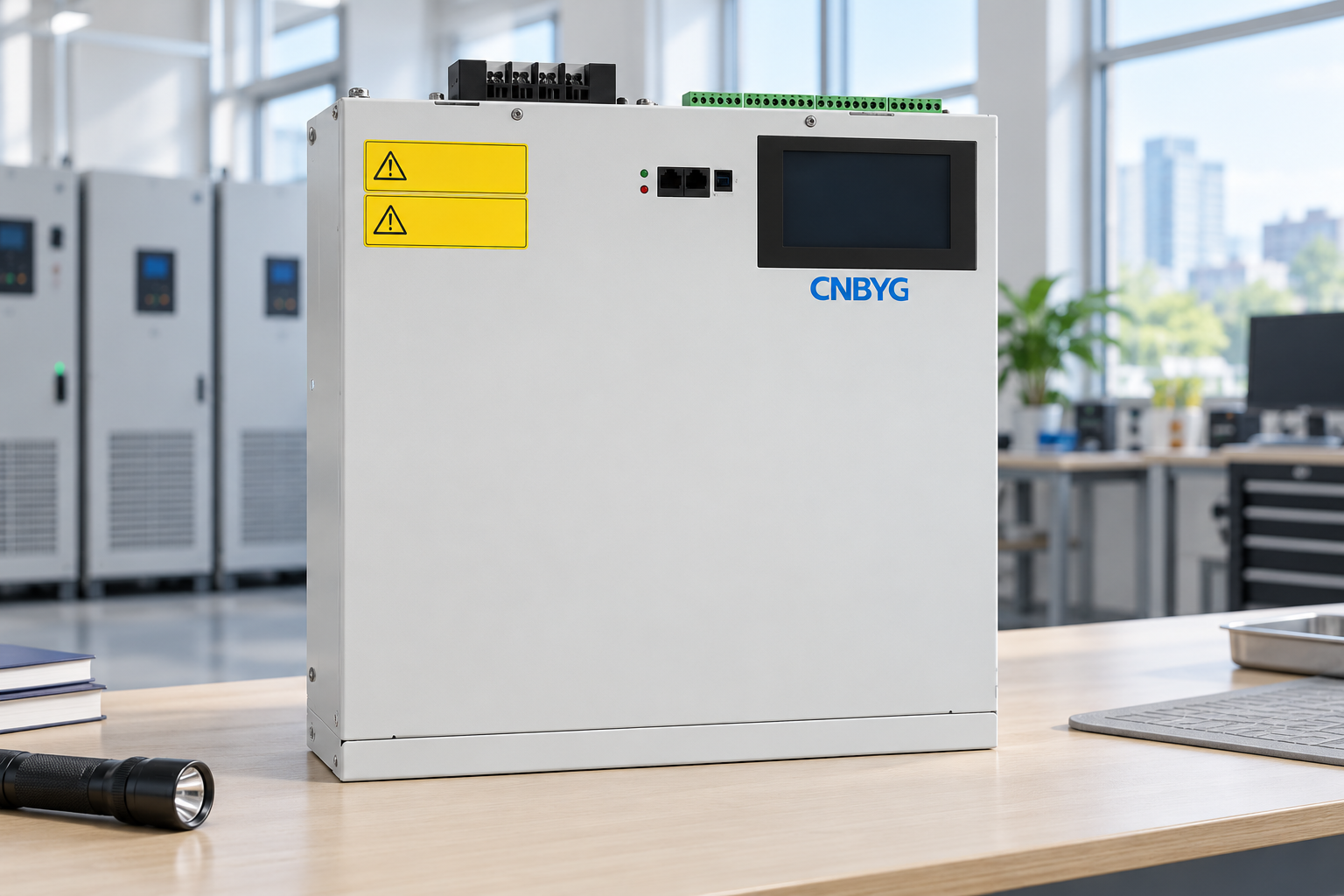
The product-reference illustration shows only a disconnected enclosure in an engineering workroom. It is not an installation diagram, an island-operation test or proof of grid-forming capability. Warning labels are simplified; actual equipment instructions govern the installation and operating conditions.
Where permission to operate a device changes by mode, record that arrangement in the approved control and interlock design. Do not improvise switching instructions from a blog article. The source controller, protection engineer and compensation supplier need a shared understanding of enabled states and fault behaviour.
Turn the survey into acceptance criteria
Agree the measurement points, instrument methods, operating matrix and allowed variations before changing the system. State which limits come from the connection agreement, applicable requirements, load tolerances or equipment documentation. Avoid presenting a generic table of numbers as universally applicable to every microgrid.
Use comparable baseline and final states. Record source dispatch, available headroom, enabled loads and settings along with voltage, frequency, distortion and events. If the weather, generation or load combination differs, explain how that affects the comparison. A favourable day is not independent proof of mitigation performance.
Transitions deserve their own evidence. Retain event timing, source-controller logs and critical-load response. Do not mark islanding or reconnection as passed merely because continuous grid-connected measurements look satisfactory. Untested or unsupported modes must remain explicitly pending or excluded from the approved scope.
The final handover should include drawings, control roles, permissions by operating mode, settings, equipment documents, raw survey exports, event records and a list of conditions not tested. Review the arrangement when sources, firmware, protection settings or major loads change. Preserve the previous accepted baseline to make later changes traceable.
Further learning: power-quality monitoring
The NPTEL IIT Delhi lecture on power-quality standards and monitoring explains general measurement and assessment concepts. It is background for the survey and does not validate a microgrid controller, transition scheme or a specific AHF operating mode.

Watch Power Quality: Standards and Monitoring
Frequently asked questions
Does good grid-connected power quality prove island operation will pass?
No. Source characteristics, control roles and load combinations change. Assess island operation and transitions using the approved operating matrix and corresponding evidence.
Can an active harmonic filter form the microgrid supply?
Do not assume so. Verify the specific equipment functions. Harmonic-current compensation and establishing voltage and frequency are different requirements.
Which bus should be measured?
Choose locations that answer the project questions, commonly including the interface and relevant critical or nonlinear-load feeders. A single instrument location does not necessarily describe the whole microgrid.
What should a microgrid power-quality enquiry contain?
Provide the verified drawing, source control roles, permitted operating modes, source and load records, synchronized power-quality measurements, existing support devices, model documentation and acceptance criteria.