Detuned Reactor Inductance Tolerance: Measurement and Review
Detuned-reactor inductance tolerance is the permitted difference between a reactor’s specified inductance and its measured value under defined test conditions. It matters because a capacitor-reactor branch depends on both inductance and capacitance: changes in either can shift its series-resonance frequency and operating duty. Do not apply a generic tolerance to every reactor or accept a part solely because its nameplate says “7%.” Obtain the exact manufacturer’s inductance, tolerance, phase-balance requirements and measurement conditions, then assess the actual capacitor-reactor combination against the approved design.
Separate inductance from detuning percentage
Inductance is a physical circuit quantity, normally expressed in henries or millihenries. Detuning percentage describes a relationship between reactor and capacitor reactance at a specified fundamental frequency. It is therefore not a complete standalone description of a reactor. The same percentage can correspond to different inductances when the capacitor, voltage, branch output or fundamental frequency changes.
A procurement record should identify which quantity is specified and what reference conditions accompany it. A supplier’s “reactance rate” is not permission to omit the branch’s capacitor data. For the broader design relationship, use capacitor and reactor matching for detuned banks. This article focuses specifically on tolerance, inspection and what a measurement can establish.
The CNBYG CKSG series reactor page lists available reactance-rate options and environmental conditions. It does not supply a universal numerical inductance tolerance for every order. Request the value and acceptance method for the exact model rather than converting a catalog family description into an unsupported test limit.
Understand how L and C move the resonance
For an ideal linear series LC pair, the resonance frequency is fr = 1/(2π√LC). L is inductance in henries, C is capacitance in farads and fr is frequency in hertz. An increase in either L or C reduces that ideal frequency. The relationship explains why assessing only the reactor tolerance leaves part of the branch variation unexamined.
OpenStax’s RLC circuit explanation describes the basic frequency-dependent interaction of inductive and capacitive reactance. The ideal calculation is useful for comparing design variations. It does not include every practical feature of an iron-core reactor, a distorted supply or an installed network, so it cannot by itself approve an industrial harmonic-filter installation.
For the same reference pair, write fr,new/fr,reference = 1/√[(Lnew/Lreference)(Cnew/Creference)]. This ratio avoids inventing absolute component values when illustrating tolerance sensitivity. The actual design still needs the correct phase or branch quantities and the connection diagram. Do not insert a line-to-line capacitance measurement into a per-element formula without confirming what the instrument and design values represent.
Work through a hypothetical sensitivity example
Suppose a design review considers a reactor at 105% of its reference inductance while capacitance remains unchanged. The ideal resonance ratio becomes 1/√1.05, approximately 0.976. That is about 2.4% below the reference frequency. The assumed 5% variation is an illustration, not a claim that a CKSG reactor is permitted to vary by that amount.
If the capacitor is also at 110% of its reference capacitance, the ratio becomes 1/√(1.05 × 1.10), approximately 0.930. The combined change is about 7.0% below reference. This example shows why separately acceptable component variations still need assessment as a pair. It does not establish a safe tuning range for a specific network.
| Hypothetical L ratio | Hypothetical C ratio | Ideal resonance-frequency ratio | Review implication |
|---|---|---|---|
| 1.000 | 1.000 | 1.000 | Reference calculation |
| 1.050 | 1.000 | 0.976 | Higher inductance lowers the ideal resonance |
| 1.000 | 1.100 | 0.953 | Higher capacitance also lowers it |
| 1.050 | 1.100 | 0.930 | Combined component changes need a paired assessment |
All values in the table are calculated examples from the ratio above, rounded to three decimals. They are not manufacturing tolerances, field-test limits or predicted performance of a CNBYG unit. The MIT AC circuits resource provides further background on ideal AC circuit quantities.
Define the measurement before comparing numbers
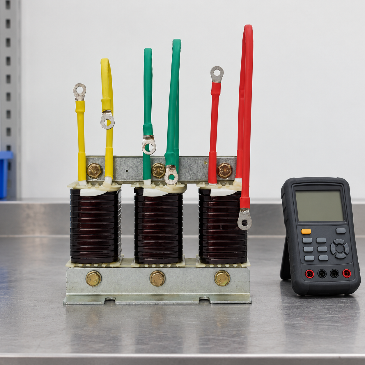
A measured inductance needs context. Record the instrument, measurement method, test frequency, test level, connection, temperature and relevant manufacturer instructions. Iron-core devices can have behavior that depends on excitation conditions. An unspecified handheld-meter reading and a factory test made under a different procedure are not automatically equivalent measurements.
Ask whether the specified inductance refers to an individual phase or another defined connection. Identify which leads belong to each winding using the supplied drawing and qualified procedures. Do not infer a connection from wire color alone or assume that a three-phase assembly can be treated as three interchangeable loose inductors under every test method.
Instrument resolution is not the same as accuracy. A display with many digits can create false confidence if the method or uncertainty is unsuitable for the acceptance limit. Include the instrument’s applicable performance information and calibration status in the record. If the result lies close to a limit, resolve the uncertainty with the supplier rather than rounding it until it passes.
Distinguish phase comparison from absolute acceptance
Comparing phases can reveal an inconsistency worth investigating, but a balanced set is not necessarily the correct inductance for the design. All phases could differ from the required value in a similar way. Conversely, phase-to-phase differences need interpretation using the manufacturer’s approved method and balance criterion, not a threshold invented from an unrelated reactor type.
Keep the raw readings as well as the calculated percentages. Calculate deviation from the stated reference using (measured − specified)/specified × 100%, while confirming that the two values describe the same conditions and quantity. A signed deviation communicates whether the measurement is above or below reference; taking only an absolute difference can hide useful direction in a troubleshooting record.
If documentation contains only a detuning percentage, ask the manufacturer for the corresponding model-specific data and acceptance procedure. The correct response to missing information is a pending disposition, not a guessed millihenry target obtained by working backwards from a nominal kvar label without the complete branch design.
Review the capacitor condition at the same time
The branch’s capacitance may differ from its nominal value, and operating history can matter when a reactor is replaced in an older bank. Use the actual approved capacitor data and suitable condition records. A replacement reactor matched to an original drawing may need reassessment if the installed capacitors no longer correspond to that drawing.
Do not use this observation as a reason to adjust reactor inductance in the field. Changes to a magnetic circuit, winding or air gap require manufacturer-controlled design work and can affect more than the small-signal value displayed by an instrument. Record the discrepancy and obtain an approved solution for the coordinated branch.
For the separate capacitor-condition question, read capacitor capacitance loss: causes and limits. Keep maintenance diagnosis, component acceptance and network harmonic performance as distinct conclusions. A satisfactory capacitance measurement does not establish that the whole installation meets a power-quality requirement.
What the purchase specification should request
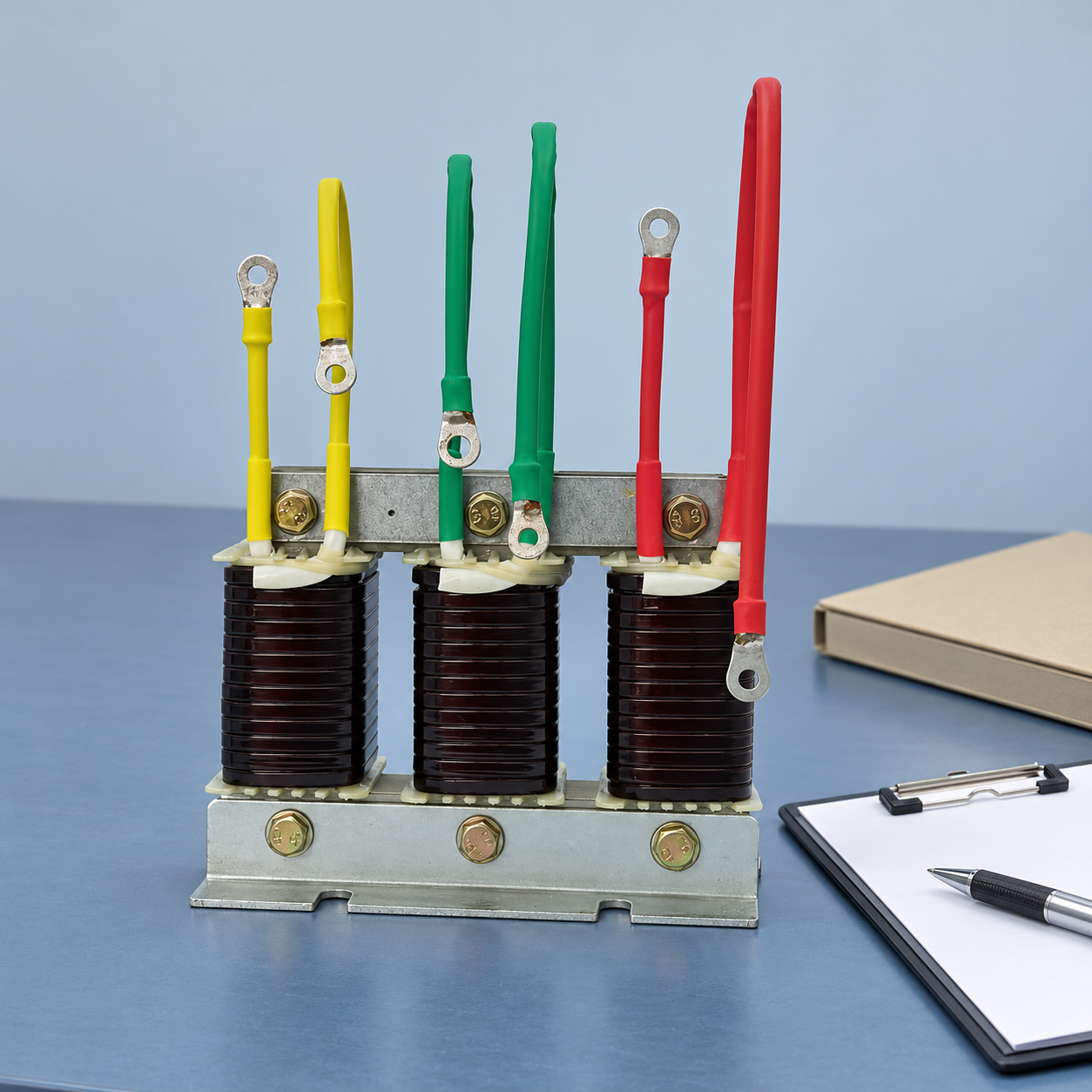
Identify system frequency and voltage, required branch duty, capacitor data, connection and the intended detuning design. Ask for the exact reactor identification, specified inductance, applicable tolerance and phase-balance criterion, together with the test method used to demonstrate conformity. Include thermal duty, environmental conditions and protection requirements as separate specifications.
State which evidence is required at delivery and which checks are planned during commissioning. A factory report should be traceable to the supplied equipment and the appropriate model or batch. A generic catalog certificate does not resolve a disputed reading on an unidentified unit. Agree on the procedure for nonconforming or uncertain results before the equipment arrives.
The detuned reactor calculation guide supports the wider sizing workflow. It should complement the ordered component’s documentation, not replace the manufacturer’s acceptance values. Treat any deviation from the approved combination as a review item, even when an alternative component appears mechanically convenient.
Safe inspection and final disposition
Inspection and measurement must be carried out by qualified personnel after the relevant circuit has been isolated and stored energy addressed under the approved procedure. A reactor in a capacitor bank is part of an assembly that may contain hazardous retained charge. An open contactor or dark controller display is not proof that touching leads is safe.
If results are inconsistent, preserve the unit identification, photographs, raw measurements, method and operating history. Ask the supplier to determine whether the issue is measurement comparability, documentation, a component mismatch or a defect. Do not accept or reject equipment solely on the basis of a single unexplained meter number.
The final record should state exactly what was established. “Inductance accepted under the specified method” is narrower than “bank performance passed.” Network behavior still depends on the complete installation, including voltage distortion, source impedance, loading, protection and the actual capacitor-reactor combination.
Further learning
Watch the capacitive-reactance lesson
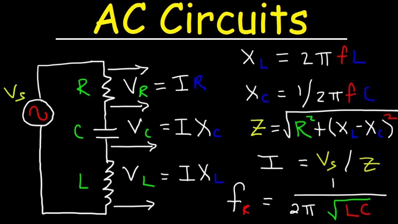
The educational RLC lesson explains the circuit relationships behind resonance. It does not provide a model-specific acceptance tolerance or authorize measurement on an energized bank.
Frequently asked questions
Is 7% the same as an inductance tolerance?
No. A detuning or reactance percentage describes a reactor-capacitor relationship at a reference frequency. Inductance tolerance describes permitted variation in a specified inductance under defined conditions.
Does CNBYG publish one inductance tolerance for every CKSG reactor?
The current product-family page does not establish a universal numerical tolerance. Obtain the exact ordered model’s value, phase-balance requirement and measurement procedure.
Can a handheld LCR reading be compared directly with a factory report?
Only after confirming that the quantities, connections, frequency, excitation and other relevant conditions are comparable. Instrument uncertainty must also be suitable for the acceptance decision.
Can a reactor pass inspection while the branch still needs review?
Yes. Component acceptance does not establish the entire bank’s harmonic performance. Capacitance, voltage, network conditions and the coordinated design still matter.