

Ct location, polarity, wiring, and commissioning evidence for apf integration should begin with a documented electrical boundary, representative operating record, and a defined decision. A meter reading, a component nameplate, or a single switching event does not by itself establish the cause, the required equipment, or the acceptance criteria.
Direct answer
Ct location, polarity, wiring, and commissioning evidence for apf integration should begin with a documented electrical boundary, representative operating record, and a defined decision. A meter reading, a component nameplate, or a single switching event does not by itself establish the cause, the required equipment, or the acceptance criteria.
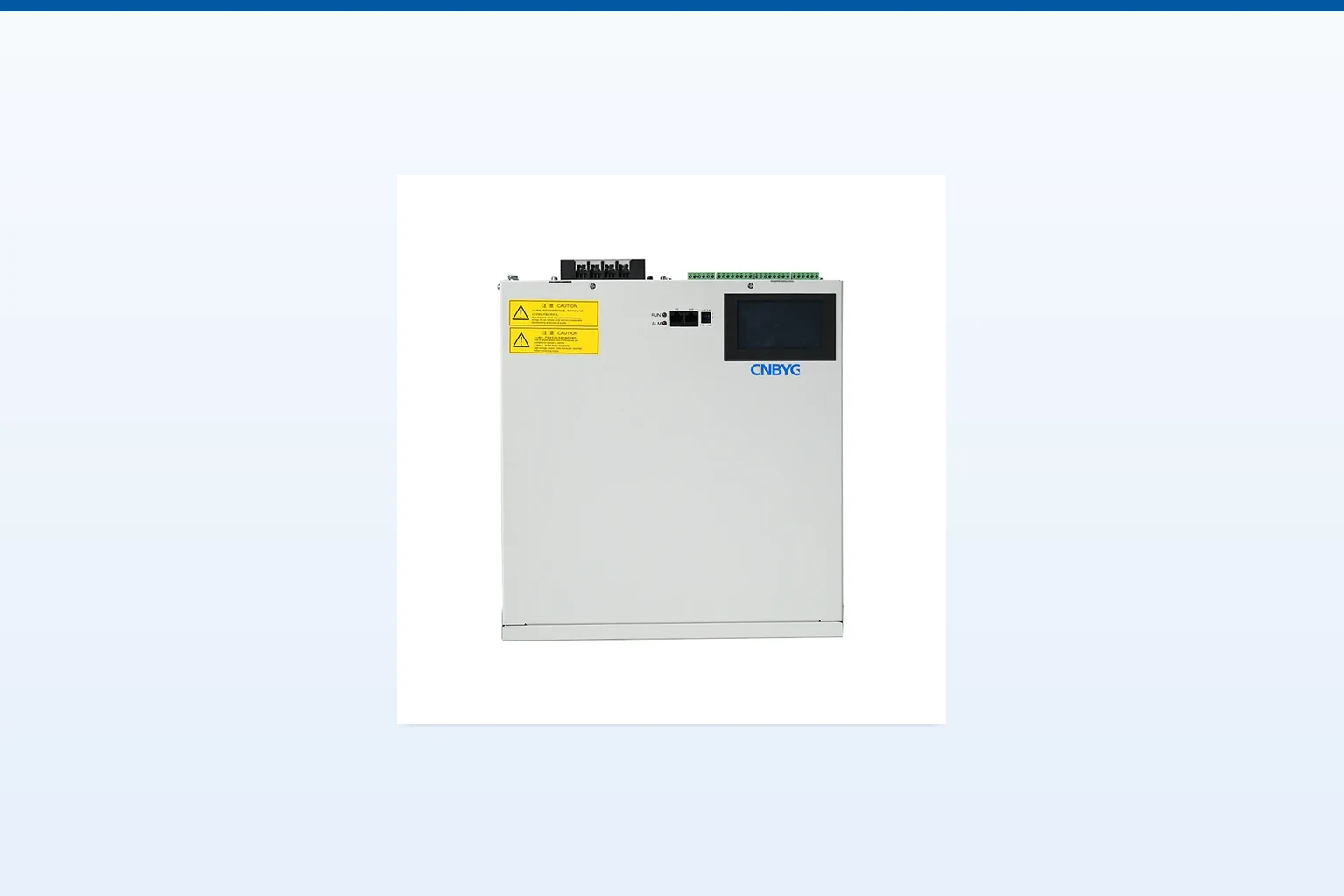
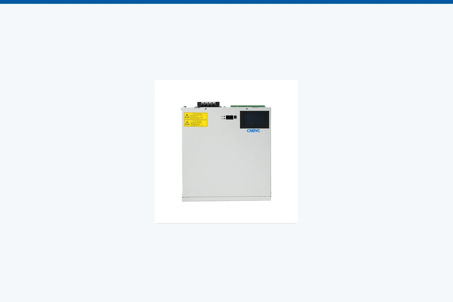
CNBYG can discuss AHF Active Harmonic Filter product-line context when the recorded evidence supports a defined objective. It cannot establish This is an installation and signal-integrity guide, not APF capacity sizing, a protection-study substitute, or a guarantee of post-installation performance. from an article. For broader navigation, see Power Quality System Guides.
Part 1. Start with the decision boundary
An active harmonic filter can only respond to the current reference presented by its CT circuit. CT placement and wiring therefore begin with the compensation boundary: identify the monitored feeder or bus, current direction, polarity convention, phase correspondence, routing, protection, and the commissioning test that will prove the signal.
At the APF reference CT location and the compensated bus or feeder, a local measurement and a system-boundary result are not interchangeable. The record should state meter location, voltage reference, CT orientation, ratio, time aggregation, operating state, and concurrent loads. Without those details, a reading can be useful for troubleshooting but unsuitable for a procurement or acceptance decision.
CNBYG can discuss its AHF Active Harmonic Filter product line when the project objective is defined. It cannot establish This is an installation and signal-integrity guide, not APF capacity sizing, a protection-study substitute, or a guarantee of post-installation performance. from an article, a photograph, or a nameplate. The Power Quality System Guides provide wider first-party navigation for a measurement-led review.

Part 2. Build an operating record before changing equipment
For this topic, the log should cover normal load, reduced load, APF enabled and disabled states, bypass or maintenance states, and representative nonlinear-load events. Keep marked CT drawings with phase labels, ratio, polarity marks, terminal numbers, and the APF configuration used for each commissioning capture. A representative record also identifies major nonlinear loads, existing capacitors, reactors, filters, transformer configuration, protective devices, and any operational change that coincides with the observed condition.
| Measurement question | Project input | Decision supported |
|---|---|---|
| What occurs at the local connection point? | Current and voltage trends, spectrum, CT position, load state | Source characterization and installation review |
| What occurs at the project boundary? | Bus data, transformer and upstream information, demand trend | System-level target definition |
| Does the condition repeat? | Time-stamped operating log across representative states | RFQ scope and commissioning comparison |
| What is already connected? | Single-line, equipment inventory, switching or control data | Interaction and integration review |
Avoid collecting a single convenient snapshot and treating it as a design basis. A run during low output, a maintenance state, or an isolated load can conceal the interaction present during normal production. Conversely, one exceptional event does not automatically define a continuous requirement.
Part 3. Separate standards context from a device decision
The IEEE 519 overview provides useful context for harmonic control discussions, but it does not prescribe a default component setting, an installation arrangement, or an acceptance result for every network. The responsible team must define the applicable point, data set, source impedance assumptions, operating cases, and contractual requirement.
Harmonic current, reactive-power behavior, voltage variation, switching transients, protection operation, and thermal conditions may coexist without having one cause or remedy. Keep each question connected to its own evidence. This prevents a component from being selected to solve a condition that has not been tied to the documented boundary.
The NEMA MG 1 reference is relevant as general motor-system context, not as proof of compatibility or outcome at this site. Project documents and qualified engineering review remain necessary for a specific installation.
Part 4. Compare integration paths without defaulting to a product
An appropriate path follows the stated objective and the measured record. Existing equipment may already influence the result; changing one element without considering the bus, transformer, controls, protection, and operating schedule can create an incomplete scope.
| Option category | May be considered when | Must be confirmed |
|---|---|---|
| AHF Active Harmonic Filter | measured harmonic current is the stated objective and the CT reference and installation arrangement are verified | Connection point, capacity basis, controls, heat, protection, and acceptance method |
| Passive components | A network study identifies a fixed or tuned function | Resonance, switching duty, network data, component ratings, and physical installation |
| Operational or upstream change | Source configuration or schedule is material | Owner responsibility, utility coordination, and implementation path |
| Further measurement | The source or boundary remains uncertain | Meter plan, operating states, duration, and comparison method |
For a product-line discussion, see CNBYG AHF Active Harmonic Filter. The page is not a substitute for the project study. Related reading on this technical guide adds neighboring system context.
Part 5. Prepare the RFQ and commissioning record
An RFQ is clearer when it includes a single-line diagram, nominal voltage and frequency, transformer details, measurement files or representative summaries, load schedule, existing equipment list, proposed connection location, protection information, cable routes, space, cooling or environmental conditions, communication needs, and the decision the owner expects the equipment to support.
Commissioning should compare like with like. Use the agreed meter positions, operating state, CT convention, time window, and acceptance method. Record what major loads were running, which stages or control modes were active, and whether the installation arrangement matches the approved drawing. A changed operating state or different meter position can alter a result without demonstrating an equipment change.
Where the project spans related concerns, this application guide helps frame an adjacent measurement-led discussion. It does not remove the need to document this article’s specific boundary.
Part 6. Apply the fit boundary before requesting equipment
This article is intentionally limited: This is an installation and signal-integrity guide, not APF capacity sizing, a protection-study substitute, or a guarantee of post-installation performance. The role of the planning record is to make uncertainty visible early enough to set a suitable scope. Regulated, critical, or unusual installations need the responsible owner, system engineer, utility where applicable, and qualified specialists to review the actual project data.
Before asking CNBYG for a product discussion, identify the objective, evidence period, boundary, present equipment, integration constraints, and decision owner. Use the CNBYG contact page to provide the available records. A complete inquiry supports a focused response; it does not replace a study, certification decision, or site commissioning process.
Frequently Asked Questions
Where should APF current transformers be placed?
Place them at the electrical location that represents the defined compensation boundary, following the approved single-line and manufacturer integration documentation. A feeder CT and a main-bus CT answer different control questions.
Why does CT polarity matter for an active harmonic filter?
Polarity establishes the direction of the measured current. A reversed reference can cause incorrect compensation behavior or commissioning alarms, so it must be checked against the approved phase convention.
Can APF CT wiring share any available cable route?
Routing must consider the installation design, separation from disturbance sources, shielding or grounding practices where specified, and accessible test points. Do not improvise a route without the approved wiring detail.
Is one measurement enough to select mitigation equipment?
Usually not. The measurement location, operating condition, duration, topology, and project objective determine whether the record is representative.
Can equipment be selected from connected load alone?
No. A project review needs measured behavior, operating profile, installation topology, existing equipment, and a defined objective.
Does this guide guarantee a compliance or operational outcome?
No. This is an installation and signal-integrity guide, not apf capacity sizing, a protection-study substitute, or a guarantee of post-installation performance. must be established and verified through the responsible project process.