VFD-heavy industrial loads
Use measured loading and operating profiles to define the problem before sizing.
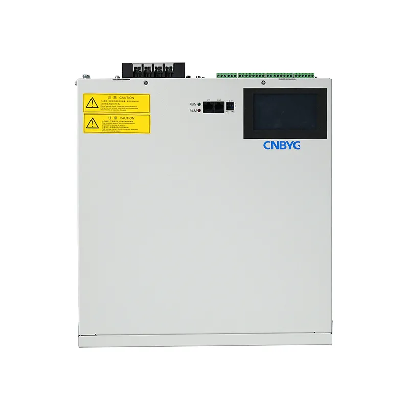
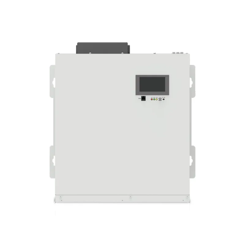

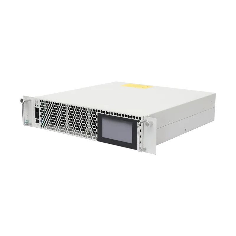
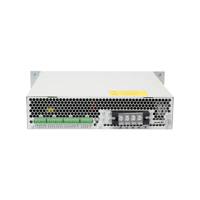
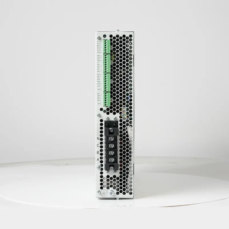
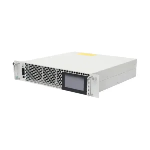
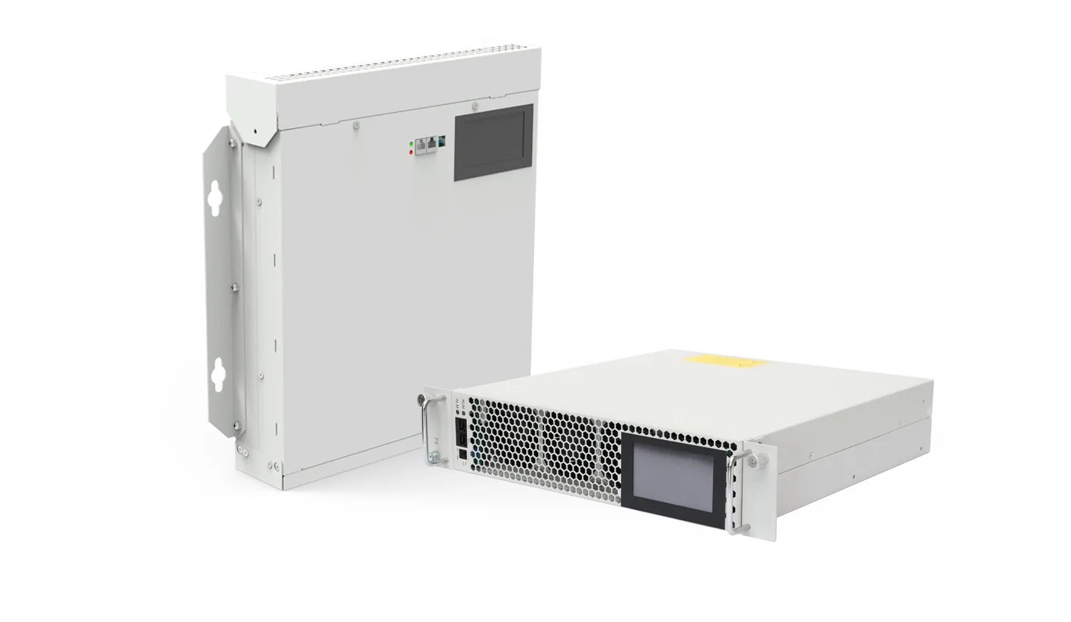
AHF active harmonic filters improve power quality and equipment reliability through harmonic control, reducing economic losses caused by equipment failures. They reduce line heating and insulation aging, enhancing electrical safety and reliability, while also reducing the resonance probability of compensation capacitors, ensuring power safety and compliance with national standards. The device reduces electromagnetic interference caused by harmonics, ensuring the normal operation of communication systems.
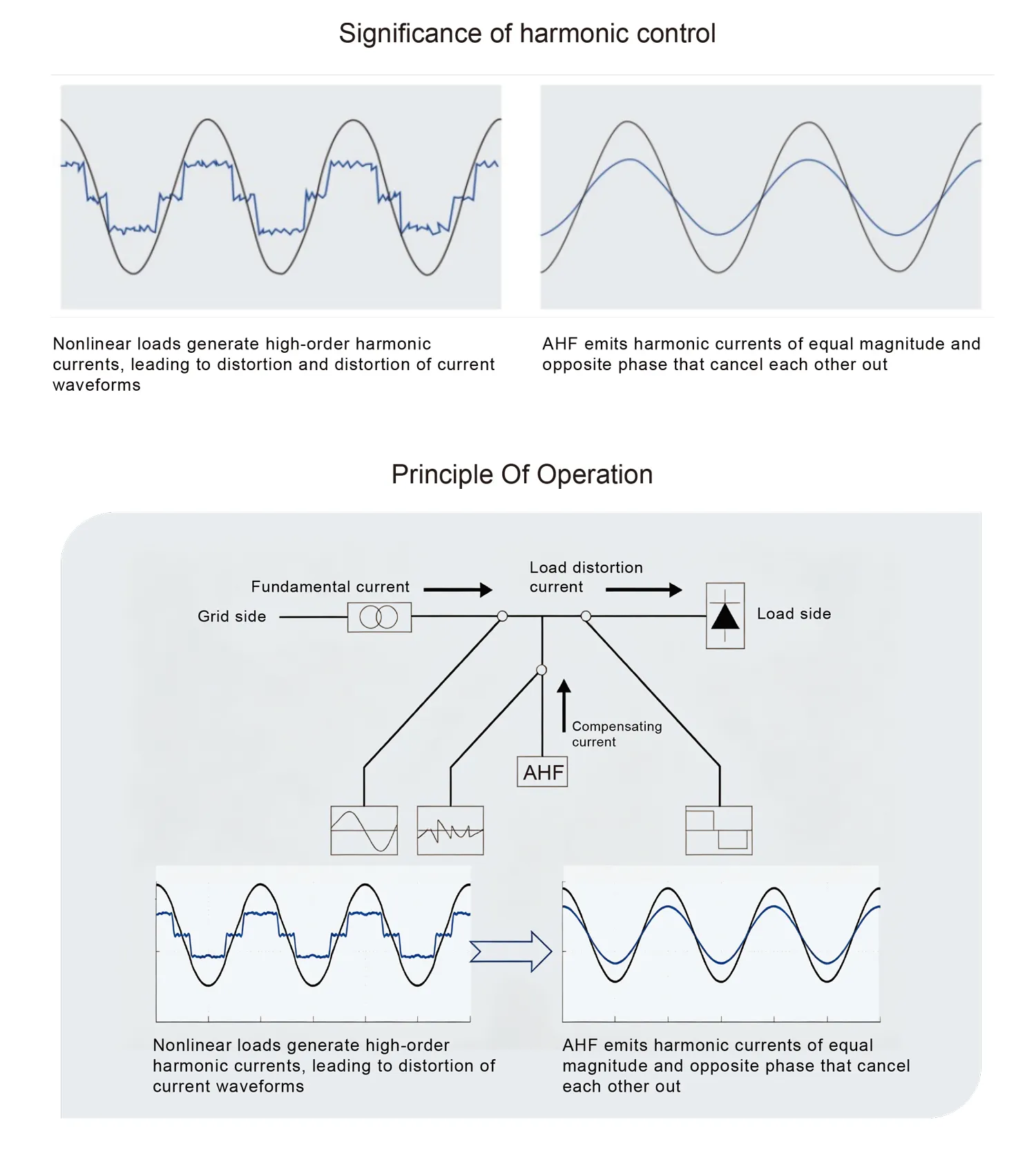
The AHF active power filter can effectively monitor harmonics and extract harmonic currents from them. The device emits inverse harmonic currents through IGBT, completely suppressing harmonics at the device connection point, and avoiding greater losses caused by harmonics flowing into circuit breakers or transformers. At the same time, the device can also manage reactive power and three-phase imbalance phenomena, truly achieving intelligent integrated power quality management. AHF can effectively filter out 2–50 harmonics.
AHF principle of operation:
The AHF operates by continuously monitoring the load current in real time using external current transformers (CTs). Its internal high-speed digital signal processor (DSP) extracts harmonic components and reactive current from the detected waveform, then generates a precise, opposite-phase compensation current. This compensating current is injected back into the power line through an insulated-gate bipolar transistor (IGBT) inverter, effectively canceling the harmonics and correcting the power factor. As a result, the AHF ensures that only the fundamental current at nearunity power factor is drawn from the utility, delivering clean, stable power to the grid.
Technical Specification
| TYPE | Series 230V | Series 400V | Series 500V | Series 690V |
| Capacity | 30A/50A/75A 100A/150A/200A |
30A/50A/75A 100A/150A/200A |
30A/50A/75A 100A/150A/200A |
30A/50A/75A 100A/150A |
| Voltage | 230V(+/-20%) | 400V(+/-20%) | 500V(+/-20%) | 690V(+/-20%) |
| Frequency | 50Hz(+/-5%) | |||
| Phase | 3 Phases | |||
| Response time | <5ms | |||
| Current transformer | 150:5~10,000:5 | |||
| Efficiency & Losses | Efficiency ≥97% (3ph), ≤15 W/A Loss | |||
| Function | Elimination of harmonic | |||
| Number of modules | No limitations. One monitoring module can be equipped with 32 actuator/execution modules | |||
| Communications protocol | Modbus, TCP/IP, CAN | |||
| Altitude above sea level | <2000m | |||
| Temperature | -20~+50C | |||
| Humidity | <90% | |||
| Pollution Degree | Below Level 2 | |||
| Compensation mode | Harmonic suppression/reactive power compensation/unbalance compensation,
11 modes in any combination |
|||
| Noise | <50dB | <60dB | <65dB | |
| Installation method | Wall Mounting | |||
| Standards compliance | IEEE519、IEC6100-3-6、ER G5/4、CE,EMC Compliance: EN 61000-6-4 Class A | |||
| Degree of protection | IP20 | |||
Product Size Information

| Model | Capacity(kvar) | Voltage(V) | Size(W*H*D)(mm) | Cooling |
| AHF-0.23-3L-W | 30A/50A/75A/100A/150A/200A | 230V | 480x570x175 | Forced Air Cooling |
| AHF-0.23-3L-W | 30A/50A/75A/100A/150A/200A | 230V | 480x570x175 | Forced Air Cooling |
| AHF-0.4-4L-W | 30A/50A/75A/100A/150A/200A | 400V | 480x570x175 | Forced Air Cooling |
| AHF-0.4-4L-W | 30A/50A/75A/100A/150A/200A | 400V | 480x570x175 | Forced Air Cooling |
| AHF-0.5-4L-W | 30A/50A/75A/100A/150A/200A | 500V | 480x570x175 | Forced Air Cooling |
| AHF-0.69-4L-W | 30A/50A/75A/100A/150A | 690V | 480x570x175 | Forced Air Cooling |
The specification is limited to standard types; other dimensions are available upon request.
Technical Specification
| TYPE | Series 230V | Series 400V | Series 500V | Series 690V |
| Capacity | 30A/50A/75A 100A/150A/200A |
30A/50A/75A 100A/150A/200A |
30A/50A/75A 100A/150A/200A |
30A/50A/75A 100A/150A |
| Voltage | 230V(+/-20%) | 400V(+/-20%) | 500V(+/-20%) | 690V(+/-20%) |
| Frequency | 50Hz(+/-5%) | |||
| Phase | 3 Phases | |||
| Response time | <5ms | |||
| Current transformer | 150:5~10,000:5 | |||
| Efficiency & Losses | Efficiency ≥97% (3ph), ≤15 W/A Loss | |||
| Function | Elimination of harmonic | |||
| Number of modules | No limitations. One monitoring module can be equipped with 32 actuator/execution modules | |||
| Communications protocol | Modbus, TCP/IP, CAN | |||
| Altitude above sea level | <2000m | |||
| Temperature | -20~+50C | |||
| Humidity | <90% | |||
| Pollution Degree | Below Level 2 | |||
| Compensation mode | Harmonic suppression/reactive power compensation/unbalance compensation, 11 modes in any combination | |||
| Noise | <50dB | <60dB | <65dB | |
| Installation method | Rack Mounting | |||
| Standards compliance | IEEE519、IEC6100-3-6、ER G5/4、CE,EMC Compliance: EN 61000-6-4 Class A | |||
| Degree of protection | IP20 | |||
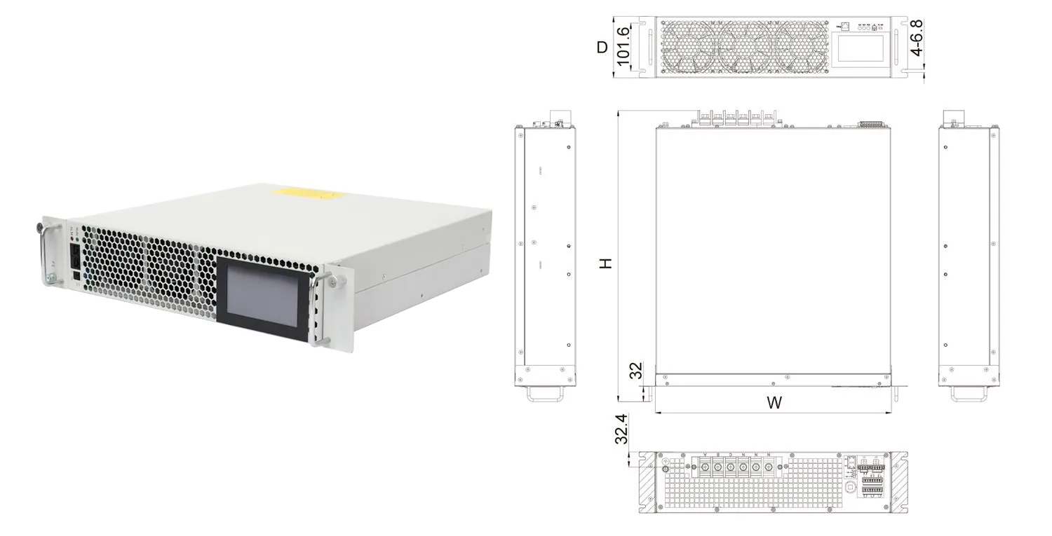
| Model | Capacity(kvar) | Voltage(V) | Size(W*H*D)(mm) | Cooling |
| AHF-0.23-3L-W | 30A/50A/75A/100A/150A/200A | 230V | 480x570x175 | Forced Air Cooling |
| AHF-0.23-3L-W | 30A/50A/75A/100A/150A/200A | 230V | 480x570x175 | Forced Air Cooling |
| AHF-0.4-4L-W | 30A/50A/75A/100A/150A/200A | 400V | 480x570x175 | Forced Air Cooling |
| AHF-0.4-4L-W | 30A/50A/75A/100A/150A/200A | 400V | 480x570x175 | Forced Air Cooling |
| AHF-0.5-4L-W | 30A/50A/75A/100A/150A/200A | 500V | 480x570x175 | Forced Air Cooling |
| AHF-0.69-4L-W | 30A/50A/75A/100A/150A | 690V | 480x570x175 | Forced Air Cooling |
The specification is limited to standard types; other dimensions are available upon request.
CNBYG’s Active Harmonic Filter (AHF), also called an Active Power Filter (APF), is a product-line entry for projects where measured harmonic current, reactive-power demand, or three-phase imbalance needs technical review. Confirm the connection point, load profile, harmonic spectrum, installation topology, and required acceptance criteria before selecting a model or rating.
Use measured loading and operating profiles to define the problem before sizing.
Review neutral loading and the relevant measurement point as part of the project.
The article explains planning inputs; it does not replace a compliance study.
Use the system hub when measurements identify separate harmonic and reactive-power objectives.
Product data should be evaluated against these inputs; no generic page can guarantee a particular harmonic or compliance result.
Use these articles to frame the technical question before requesting a project recommendation.
Variable-speed drives, welding equipment, and automation loads require measurement before selecting a mitigation path.
Treat harmonic loading, neutral current, and continuity requirements as a coordinated design review.
Inverter and charging loads can change operating conditions; review data at the relevant connection point.
Welding, shore-power interfaces, and marine operating constraints need a project-specific assessment.
These terms are commonly used for active filtering equipment. Confirm the actual product function and project configuration from the technical documentation and application review.
No. Sizing needs measured harmonic current and project-specific operating conditions in addition to the load inventory.

Interested in this product? Fill out the form below and our sales team will get back to you within 24 hours.