


An active harmonic filter not reducing THD does not automatically mean the filter has failed. First establish whether you are comparing current THD, voltage THD, or total demand distortion at the same measurement point under comparable loading. Then verify the filter is actually injecting compensation current, its current transformers represent the intended conductors, and its settings and available capacity match the measured harmonic demand. A low-load percentage, an upstream voltage disturbance, or a measurement taken on the wrong side of the filter can make useful compensation appear ineffective. This guide separates those cases before recommending equipment changes.
Start with the measurement, not a replacement filter
Record the meter location on a single-line diagram. Distinguish the incoming supply, the load feeder, and the filter branch. A shunt filter supplies part of the load’s harmonic current locally. The nonlinear load can continue drawing distorted current while the upstream source current improves. A clamp around the load cable alone may therefore show little change even when the filter is working correctly.
Use the same analyzer, wiring configuration, current range, averaging method, and harmonic bandwidth for both observations. Record operating loads, production state, capacitor stages, generator operation, and other filters. Comparing a fully loaded shift against an idle weekend is a load comparison rather than a controlled filter test. Keep original recordings so another engineer can reproduce the conclusion.
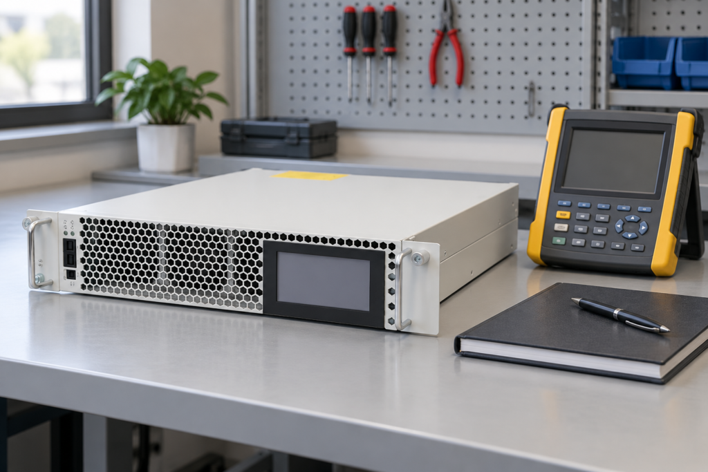
The CNBYG active harmonic filter product page provides the relevant equipment context. Product appearance alone does not establish a unit’s current rating, compensation priorities, or supported topology. Confirm those items against the exact installed model and its approved documentation before diagnosing performance.
Separate THDi, THDv, and TDD
Current THD compares harmonic current with the fundamental current. For the measurement bandwidth being used, THDi is the root-sum-square of harmonic current components divided by the fundamental current, multiplied by 100 percent. Voltage THD uses the corresponding voltage components and fundamental voltage. TDD uses an agreed demand-current reference rather than the instantaneous fundamental current. These quantities answer different questions.
Consider a deliberately simplified arithmetic example. If harmonic current is 20 A and fundamental current is 100 A, THDi is 20 percent. If the operating load later falls so fundamental current is 20 A while harmonic current becomes 8 A, THDi is 40 percent. The percentage rose even though harmonic amperes fell. This is an illustration of denominator sensitivity, not a CNBYG test result or an acceptance limit.
Always retain harmonic amperes, fundamental current, total RMS current, and individual harmonic orders alongside the percentage. If an acceptance requirement concerns the point of common coupling, do not substitute a convenient downstream feeder measurement. The IEEE 519 standard information explains the standard’s harmonic-control scope. Formal acceptance requires the applicable edition, measurement boundary, and agreed evaluation method; one instantaneous THDi display cannot establish compliance.
A practical diagnostic decision table
| Observation | Evidence to collect | Next engineering check |
|---|---|---|
| Load current THD unchanged, source current improves | Simultaneous source and load waveforms | Confirm the original test point was appropriate |
| THDi rises at light load while harmonic amperes fall | Fundamental current and harmonic RMS values | Compare equivalent operating conditions |
| Filter shows no compensation output | Enable state, permissives, event log, branch current | Review operating mode and protective conditions |
| Output reaches its permitted current | Per-phase harmonic demand and compensation priorities | Assess capacity and allocation under actual load |
| Current improves but voltage THD remains high | Source voltage trend and upstream disturbance records | Investigate supply impedance and background distortion |
| One phase improves and another does not | Phase identification, CT records, per-phase spectra | Check topology, sensor mapping, and phase association |
| Improvement disappears intermittently | Thermal events, load changes, parallel-unit status | Correlate events before changing settings |
The table describes diagnostic paths, not permission to alter an energized installation. Measurements and electrical work require qualified personnel using suitable equipment and the site’s isolation procedure. Never open a current-transformer secondary while its primary carries current. Follow the installed CT documentation and approved shorting arrangements whenever sensor work is necessary.
Verify current-transformer location and phase association
Compare the actual CT positions with the approved control drawing. Different filters use different sensing arrangements, so a source-side arrangement is not universally interchangeable with a load-side arrangement. Establish which currents the controller is intended to observe and whether a parallel filter or capacitor bank lies inside that boundary.
Then reconcile phase labels, polarity marks, and configured ratios with recorded documentation. A physically plausible installation can still associate one current channel with the wrong voltage phase. CT ratio errors can distort the controller’s interpretation of current magnitude. Polarity errors can affect the inferred direction of compensation. Do not correct these by trial-and-error changes while watching a percentage display.
The separate AHF CT placement and wiring guide covers installation boundaries, while the CT ratio error guide addresses scaling. This article concentrates on interpreting ineffective compensation after those installation records have been checked.
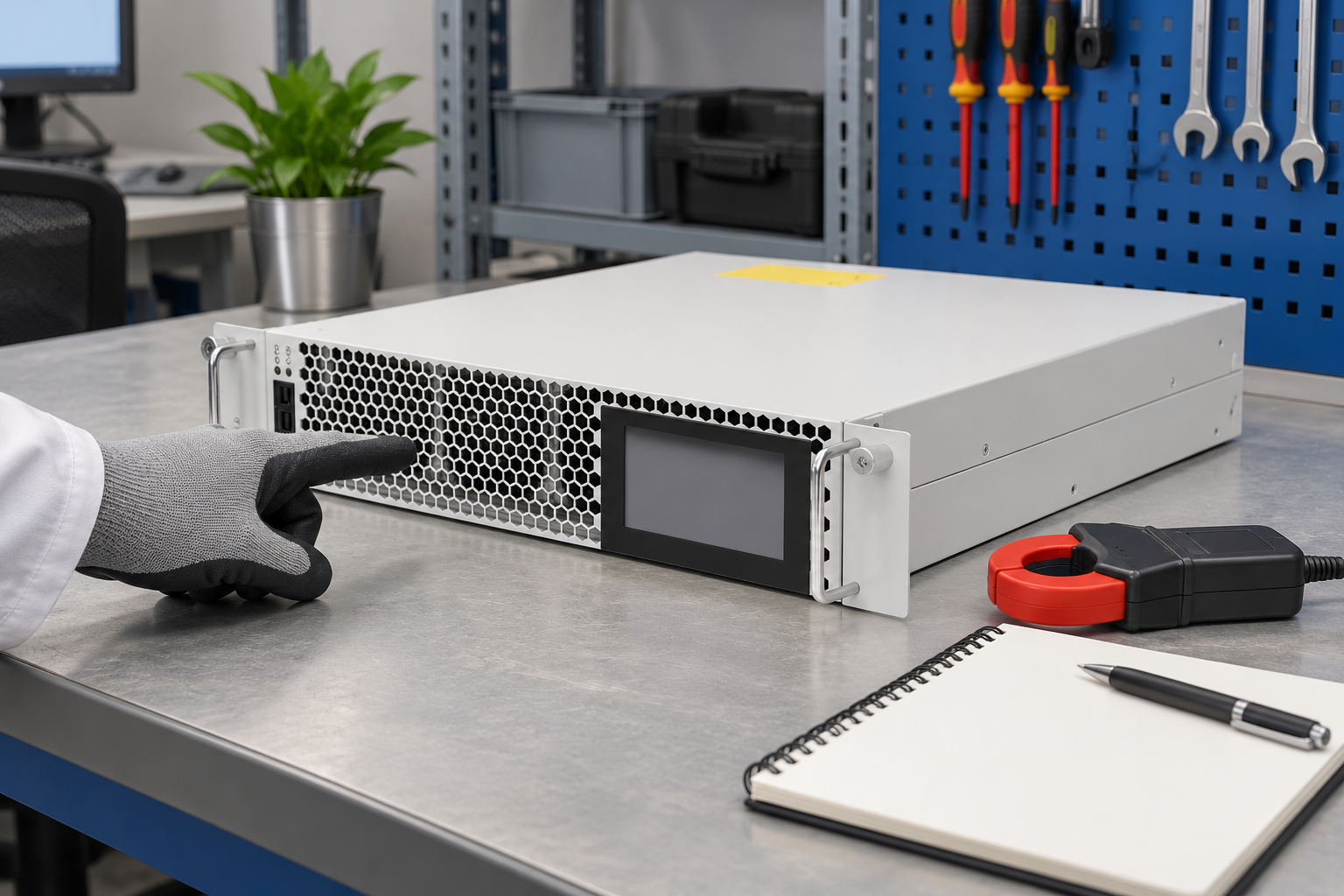

The illustration shows the referenced closed rack module before inspection. It does not show a live test, a wiring instruction, or a verified sensor connection. An exterior inspection can identify blocked airflow or obvious damage, but cannot prove the electrical sensing arrangement is correct.
Confirm operating mode and available compensation capacity
Read the controller’s current operating state and event history. A healthy display is not proof that harmonic compensation is enabled. The unit may be waiting for an interlock, operating in a different mode, limited by a protection condition, or allocating current to other configured objectives. Use the exact manual to interpret messages; alarm names and thresholds are model dependent.
Observe output current across a representative load interval. If the filter continuously reaches its permitted output, the remaining harmonics may reflect a capacity limit rather than faulty cancellation. Determine which harmonic orders and phases remain dominant. A three-phase total can conceal a heavily loaded phase, and a nominal rating does not describe every operating condition.
Check whether reactive-current or imbalance compensation shares the available current budget. Record priorities before proposing changes. Do not disable a protection function or raise a current limit to force a lower THD reading. Any change must remain within the manufacturer’s operating envelope and the installation design.
For systems with multiple modules, identify which units are online and whether their intended coordination is functioning. The loss of one module can leave the others operating normally while overall compensation becomes insufficient. Compare the expected available capacity with actual healthy units rather than the original purchase quantity.
Investigate voltage distortion and resonance separately
An AHF primarily addresses the current components within its designed control capability. It cannot guarantee that an upstream distorted voltage waveform will become clean at every downstream bus. Background supply distortion, transformer and cable impedance, and other nonlinear loads can affect the voltage observed at the meter.
Record supply voltage with the relevant load states. Where safe and approved, compare the plant measurement with an upstream reference or utility investigation. Avoid attributing every voltage harmonic to the nearby filter. If the voltage distortion was already present before the filter operated, the corrective action may involve a different boundary or source.
Capacitor banks and network impedance also change the harmonic environment. Review whether a capacitor-stage change coincides with a rising harmonic order. Do not add capacitance or alter detuning based solely on total THD. A resonance assessment needs the installation configuration, equipment data, and harmonic spectrum, not a universal rule about one preferred reactor percentage.
The IEC 61000-4-30 measurement standard page is a useful reference for power-quality measurement methods. Select instrument capabilities against the measurement purpose and applicable standard; the presence of a multifunction display does not establish certified power-quality measurement performance.
Build a comparable before-and-after record
Agree on the measurement boundary and a safe test plan before changing operating state. Record a baseline under a stable, representative production condition. When authorized by the responsible engineer, compare filter operation using the same loads and instrument configuration. Some installations cannot tolerate deliberate switching for a test; use naturally occurring operating intervals or an approved commissioning procedure instead.
Capture individual harmonic magnitudes, current and voltage RMS values, fundamental values, and the filter’s operating status. Include enough time to observe the load variation relevant to the original complaint. A single screenshot can hide warm-up behavior, intermittent overload, or a production cycle that creates short bursts of distortion.

Save settings exports, event timestamps, instrument configuration, and a marked single-line diagram with the results. Label each recording with the exact meter point and filter state. A convincing improvement is repeatable under the agreed conditions and does not depend on changing the measurement denominator or omitting a difficult interval.
Decide whether to correct installation, settings, or selection
Use the collected evidence to choose the smallest justified action. Incorrect measurement placement requires a corrected test. Documented CT or phase-association errors require installation correction under an approved procedure. A disabled function or inappropriate priority requires a settings review. Insufficient healthy capacity requires a load-based selection assessment. An upstream disturbance requires investigation beyond the filter branch.
For a supplier review, provide the actual model, current rating, topology, firmware identification if available, CT specifications, approved wiring diagram, operating logs, and representative spectra. Explain the intended acceptance point and the remaining problem in amperes and voltage components as well as percentages. This evidence supports a meaningful response and avoids purchasing another unit to solve a measurement error.
Do not declare success merely because the displayed THDi briefly falls. Recheck protection status, temperature, operating stability, and the agreed acceptance measure across representative conditions. Record what changed and schedule a follow-up after a normal production interval so the corrective action can be evaluated against the original complaint.
Further learning: power quality monitoring
The NPTEL IIT Delhi lesson below explains standards and monitoring as the basis for interpreting a power-quality result. It supports the measurement sections of this guide; it does not replace the installed filter manual or provide permission to work on live equipment.

Watch Power Quality: Standards and Monitoring
Frequently asked questions
Can an AHF work while load-side THD stays high?
Yes. A shunt filter can supply harmonic current locally while the nonlinear load still draws a distorted waveform. Check the agreed upstream measurement boundary and compare source current with load current before concluding the filter is ineffective.
Why does current THD sometimes rise at low load?
THDi uses fundamental current as its denominator. When fundamental current becomes small, a reduced harmonic current can still produce a larger percentage. Compare harmonic amperes, load level, and the agreed demand-current reference where applicable.
Does a good THDi reading prove IEEE 519 compliance?
No. Formal evaluation requires the applicable standard, point of common coupling, voltage and current criteria, individual harmonic components, and appropriate measurement periods. A downstream instantaneous THDi number does not establish all of those conditions.
Should I increase filter current to improve the result?
Only an evidence-based review can determine whether capacity is limiting performance. Confirm sensing, operating mode, current allocation, protection conditions, and representative demand first. Never raise a setting beyond the documented equipment or installation rating.