


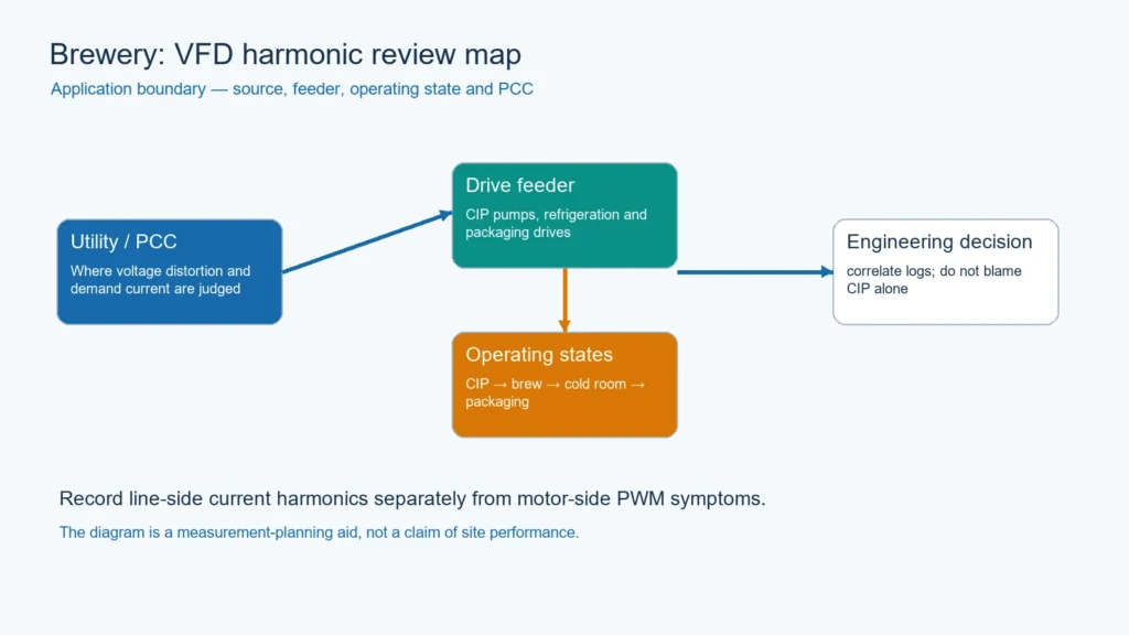
CIP, brewing, refrigeration and packaging are different process sequences. Their pumps, compressors and conveyors may share transformers or feeders, so a nuisance trip that appears during CIP is not proof that CIP chemicals or the cleaning recipe created the electrical distortion. Correlation must come before attribution.

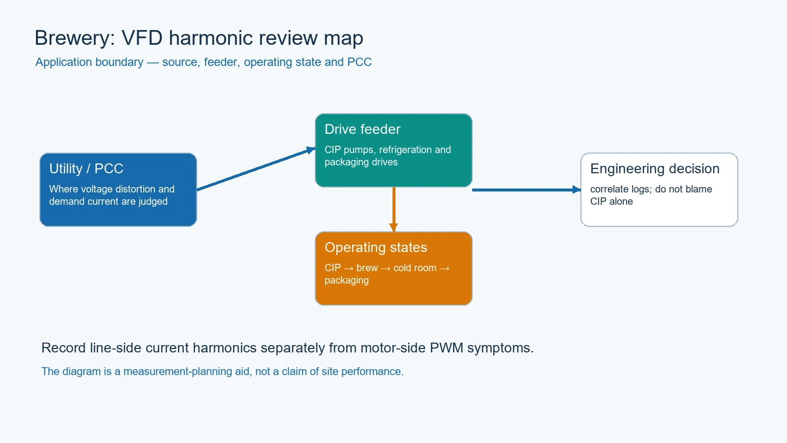
Treat CIP as a process sequence, not an electrical culprit
CIP can involve caustic, rinse, acid and sanitizing steps, but the electrical load is created by the pumps, valves, heaters, refrigeration and controls that run during each step. Paul Mueller and IGChem describe CIP as a repeatable cleaning system with its own process variables. That context helps the electrical team tag the event; it does not prove that a chemical or recipe creates harmonics.
Use a shared timeline that includes CIP step, brew state, cold-room compressor staging and packaging start/stop. If the same electrical event appears during different recipes, the common drive or feeder is a stronger lead than the recipe name.
Measure the feeder, PCC and process state together
Capture phase current, voltage, spectrum, demand current and power factor at the suspected feeder and upstream PCC. Add controller alarms, pump commands, compressor staging and packaging state. Keep the CT orientation and meter setup fixed across the comparison.
| Evidence stream | Example tag | What it can support |
|---|---|---|
| CIP process | step, flow, temperature, recipe | When the process changed |
| Drive feeder | pump or compressor group | Whether the local spectrum changed |
| PCC / main bus | same timestamp | Whether the upstream system saw it |
| PLC / protection | alarm, trip, restart | Correlation clue, not electrical proof alone |
Decide whether mitigation is local or shared
A small pump feeder may be best handled at the drive or feeder. A shared refrigeration or packaging bus may require a system-level review. VFDs.com, Fluke, CSE, Veikong and Processing all support the general sequence of identifying the non-linear source, measuring the boundary and then comparing mitigation options.
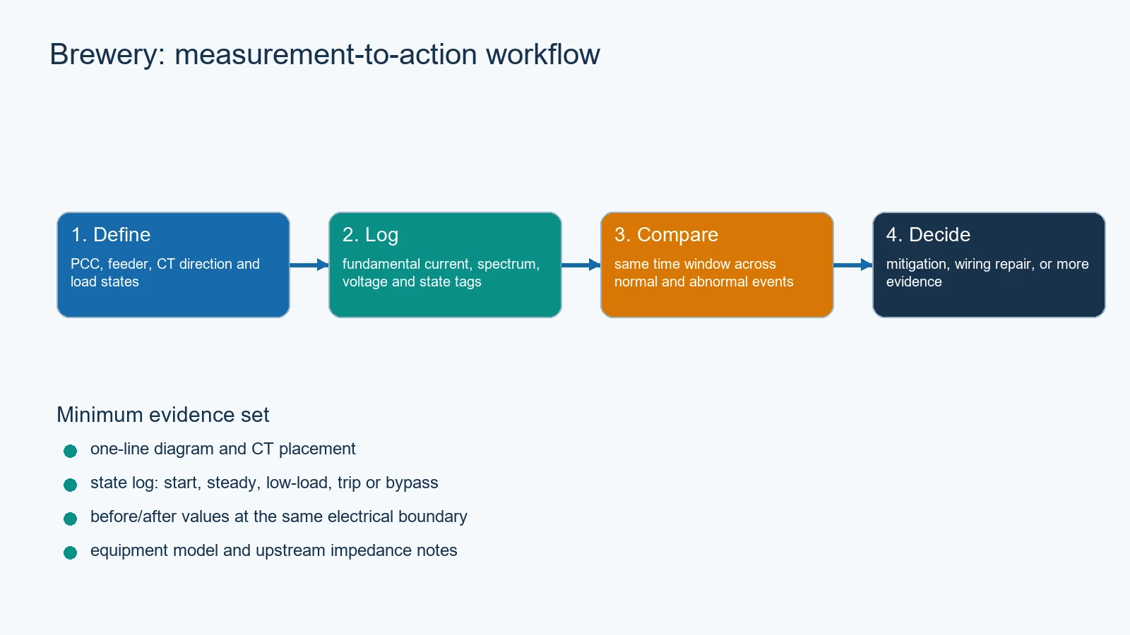
What the brewery should hand to an engineer
- A one-line showing refrigeration, CIP, brewing and packaging feeders.
- A state log with the same timestamps as the power-quality file.
- Drive topology, line reactors, DC chokes, filters and cable notes.
- Protection and PLC event records around the complaint.
- A defined acceptance boundary: feeder, main bus or PCC.

An AHF path for a measured brewery feeder
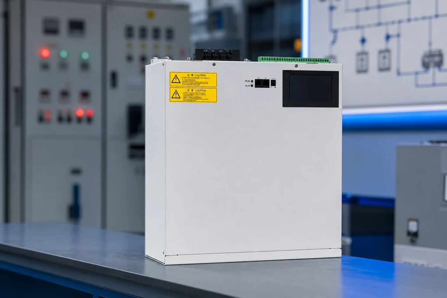
The CNBYG AHF/APF product path is a reasonable next step only when the measured problem is line-side harmonic current and the source boundary is clear. Ask for current capacity, CT arrangement, thermal/enclosure limits, bypass behavior and commissioning records. Nothing here claims that CIP, a brewery, or a specific CNBYG model has a guaranteed result.
Read the Power Quality System pillar, then the food-processing mixer review and the power-quality metering guide.
References


