Capacitor Contactor Coil Undervoltage: Diagnose Chatter Safely
Capacitor contactor coil undervoltage can cause incomplete pickup, repeated opening and closing, and damage to the switching assembly. The useful diagnosis is to establish whether the contactor receives a stable command and the correct voltage during the actual pickup event. A normal reading taken after the event can miss the cause. Separate supply voltage loss, resistance in the control path, repeated controller commands, and mechanical obstruction before replacing components. This guide addresses control-circuit investigation in low-voltage capacitor panels; it does not provide a universal minimum coil voltage or authorize energized work.
Why chatter needs a prompt investigation
A capacitor contactor is an electromagnetic switching device with a control circuit and a separate power circuit. A small AC hum can be a characteristic of the magnetic assembly, but repeated visible movement or repeated closure is a different symptom. Do not classify both simply as noise. Record whether the sound is steady, whether the armature moves repeatedly, and whether the stage indication changes with it.
In capacitor switching, each unintended closure is also another switching event. The duty of the main contacts and the surge-limiting assembly therefore matters alongside the coil condition. A burnt resistor block does not, by itself, prove that the capacitor was oversized. A successful repair should explain the initiating condition and determine which components were subsequently damaged. See the separate guide to capacitor contactor resistor failure for that component-specific assessment.
Establish a safe measurement plan first
Prepare the single-line diagram, the control schematic, the exact installed coil designation, and the panel isolation procedure. Main bus voltage and coil voltage are different quantities. A panel supplied at one voltage may use a control transformer or another source for its switching coils. Identify all supplies, including remote control circuits that remain powered when the main disconnect is open.
OSHA 1910.333 addresses deenergization, lockout, verification, and hazardous stored electrical energy. Apply the rules applicable to the installation and its jurisdiction. Capacitor discharge and absence-of-voltage verification belong in the approved work procedure. A controller OFF command is not an isolating device. Any energized diagnostic measurement requires qualified personnel and the site’s electrical safety controls; this article is a diagnostic framework rather than a live-testing instruction.
Use existing approved monitoring points or arrange instruments during an isolated condition where the procedure permits. Choose equipment with suitable voltage and measurement-category ratings. Record the instrument’s capture mode and limitations: a slow display may show an acceptable average while a short pickup-related dip occurs between updates. Do not create a suspected fault deliberately by repeatedly cycling a damaged capacitor stage.
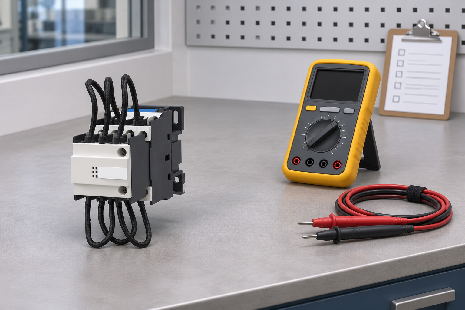
Read the installed coil information correctly
Record rated control voltage, AC or DC operation, frequency where applicable, and the manufacturer part identification. Similar-looking contactors can have different coils. An invoice description or a panel drawing may describe the intended component while the installed unit differs. A readable nameplate photograph and the approved bill of materials should agree before the diagnostic limits are selected.
CNBYG’s GJ19 switching capacitor contactor page describes a capacitor-duty assembly with current-limiting contacts and resistors. Its ordering information distinguishes coil supply voltage and frequency. Confirm the exact delivered model and manual, particularly where catalogue naming differs between a product family heading and individual model designations. This guide does not extend one catalogue operating range to every coil or installation.
Pickup conditions, holding conditions, and release conditions are not interchangeable specifications. A contactor that remains closed during a moderate dip may still fail to close correctly if the same voltage is present at pickup. Likewise, an instrument reading with the coil disconnected says little about the supply’s ability to deliver pickup demand. Compare the observed event with the relevant manufacturer operating condition, including temperature and frequency boundaries.
Separate five fault paths before selecting a remedy
The following table is a diagnostic decision aid, not a table of universal acceptance limits. Its categories describe observations that must be confirmed against the actual schematic and component documentation. Preserve the event timing so that the control command, source voltage, and coil voltage can be compared meaningfully.
| Observed evidence | Plausible fault path | Next useful check | Remedy boundary |
|---|---|---|---|
| Control source and coil voltage fall together during pickup | Supply capacity or upstream disturbance | Compare the event with other simultaneous control loads | Review source sizing and disturbance origin before replacing the contactor |
| Source remains stable but coil voltage falls | Excessive drop in the control path | Inspect documented terminals, relay contacts, and return path during isolation | Repair the identified connection or component using its approved procedure |
| Coil voltage cleanly follows repeated controller commands | Control logic or unstable input | Review command history, measured PF, and stage delays | Correct the control cause rather than raising coil voltage |
| Correct stable coil supply but incomplete mechanical closure | Wrong assembly, obstruction, or mechanical damage | Check installed identification and isolated mechanical condition | Follow manufacturer assessment or replacement requirements |
| Voltage appears present when the command is OFF | Leakage, backfeed, or measurement interpretation | Review output type, suppression devices, and instrument characteristics | Do not add a resistor or bypass without an approved circuit design |
More than one fault path can coexist. For example, a poor joint may create voltage loss and then overheat, while repeated attempts damage the contactor. Finding damaged contacts does not eliminate the need to examine the supply. Conversely, a brief recorded voltage dip is not sufficient evidence that every visible defect was caused by that dip.
Compare source voltage with voltage at the coil
Define the source measurement point precisely. The outgoing control-transformer terminals, the panel terminal strip, and the remote supply output are not equivalent points. Also define the coil measurement across its actual supply terminals according to the schematic. Measuring a conductor relative to protective earth can mislead when the control circuit is referenced differently.
If the source stays within its specified conditions while the coil supply falls, map the complete outgoing and return paths. Possible contributors include deteriorated relay contacts, loose connections, damaged conductors, unsuitable conductor length or cross-section, and incorrect interposing arrangements. Examine each path against the approved design. Do not increase transformer output voltage to conceal a localized connection problem.
If both source and coil voltage fall together, review the source loading during the event. Several contactors may pick up simultaneously following restoration of power. Their combined starting demand can differ from steady holding demand. Review transformer or supply documentation using the actual pickup sequence, not merely the sum of holding ratings. A source upgrade requires engineering review of protection, conductor ratings, and downstream compatibility.
Distinguish electrical chatter from stage hunting
Electrical chatter concerns the contactor’s inability to make or maintain a stable mechanical state under its supplied command. Stage hunting concerns the controller deliberately switching a stage repeatedly as its decision changes. Both can produce repeated clicking, but their corrective actions differ. Establish whether the controller output remains continuously ON while the mechanical assembly becomes unstable.
Review the controller’s event record where one is available, or use an approved observation method without assuming that the panel indicator captures every event. A lamp can show that an output is commanded without proving the voltage reaches the coil correctly. Likewise, an auxiliary indication may not establish the condition of every main pole. Document what each signal actually represents.
For deliberate repeated stage commands, review capacitor stage hunting prevention rather than treating every event as a failed coil. CT location, measurement polarity, target settings, minimum stage size, and application delays belong to the control investigation. Keep the original settings record and change one approved parameter at a time so that the effect remains interpretable.
Inspect the switching assembly after isolation
With the equipment safely isolated and verified, inspect for loose mounting, contamination, heat discoloration, damaged insulation, displaced leads, and evidence that the mechanism cannot close as intended. Do not file magnetic faces, lubricate mechanisms, adjust springs, or remove surge-limiting parts unless the exact manufacturer’s maintenance instructions permit that action. An apparently simple mechanical modification can alter the switching sequence.
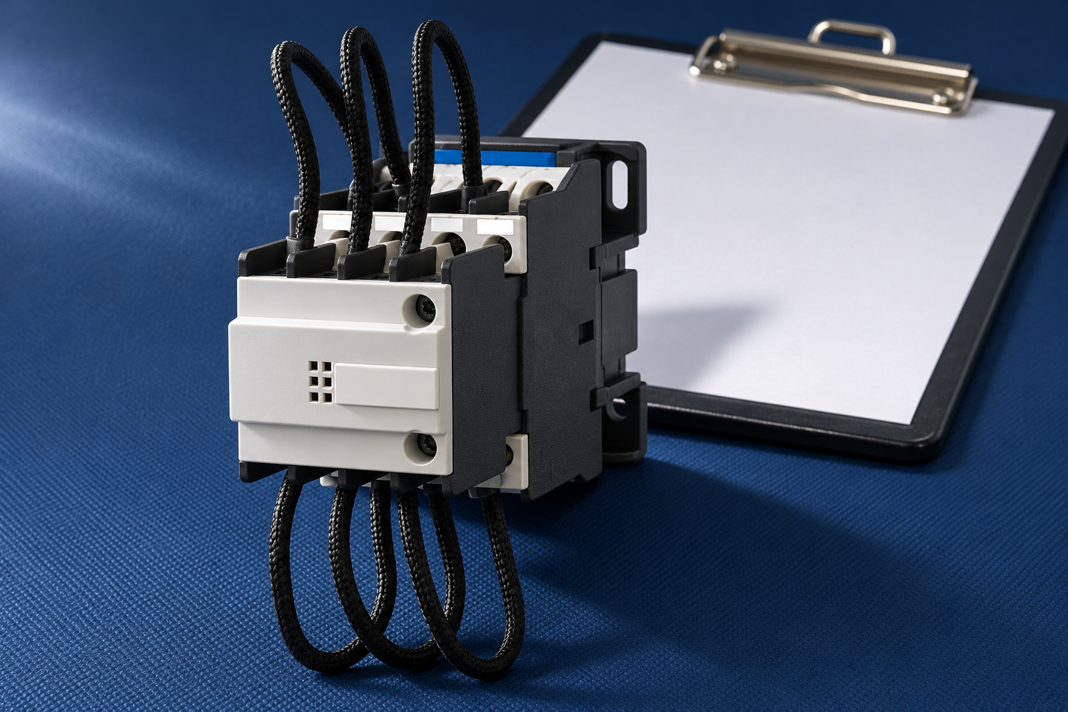
Preserve photographs before disturbing the assembly. Record the condition of the resistor leads and early-make contact assembly separately from the main terminals. Where damage prevents a reliable assessment, replacement may be the appropriate outcome, but the replacement should not be exposed to the same unresolved supply condition. Follow the supplier’s requirements on replacing an entire assembly versus individual approved parts.
Specify replacement parts with the complete duty
A replacement request should include capacitor stage duty, system voltage and frequency, the installed coil rating, auxiliary contact arrangement, mounting requirements, environmental conditions, and the approved switching sequence. Include the source of the capacitor’s actual operating current and the presence of detuning reactors. Do not select a replacement from a motor-current rating alone. The capacitor-duty contactor selection guide addresses that broader selection task.
Provide the supplier with the failed unit’s identification, event captures, command history, control schematic revision, and photographs of the damaged parts. Identify whether the proposed replacement changes pickup demand or control-output loading. A mechanically compatible unit may still require a control-circuit review. Obtain written confirmation of any differences before altering the approved panel arrangement.
Verify the repair under the conditions that exposed it
Create an acceptance plan before returning the stage to automatic operation. It should identify the approved coil supply limits, the intended command sequence, permitted test conditions, and the person responsible for release. Verify safe isolation and restoration controls first. Under the authorized commissioning procedure, confirm stable pickup and holding behavior without abnormal repetitive movement, then confirm correct stage response in the complete panel.
Include realistic supply conditions where they are within the approved test scope: simultaneous control loads, normal restoration sequences, and the operating state that originally accompanied the symptom. Do not manufacture an undervoltage event outside the equipment’s permitted operation. Record any condition that could not be reproduced. One successful unloaded operation should not be reported as proof that every intermittent cause has been eliminated.
Retain before-and-after event records, the repaired connection or replaced component identification, updated drawings where applicable, and the final release decision. If abnormal movement recurs, remove the affected stage from service under the approved procedure and reopen the diagnosis. The general automatic capacitor bank operating guide explains how the stage fits into the panel’s overall control and protection functions.
Educational background: how a contactor operates
RealPars’ introductory lesson explains the relationship between a coil and mechanically operated contacts. It is background education from an automation training publisher, not a capacitor-duty design specification or an instruction to reproduce a live wiring demonstration. The companion contactor explanation supports this basic operating principle; installed equipment instructions govern the actual coil rating and permitted work.
Frequently asked questions
Does a steady hum mean the coil voltage is too low?
Not necessarily. Distinguish a steady sound from repeated mechanical movement, then compare the actual coil supply with the installed unit’s specifications. Mounting, contamination, mechanical condition, and supply characteristics can also affect noise. Sound alone does not identify the failed component.
Can a normal meter reading rule out undervoltage?
No. A reading taken after pickup can miss a brief dip. Record the time and capture capability of the measurement, and compare the coil supply with the source during the event using the site’s approved diagnostic procedure.
Should the controller delay be increased to stop chatter?
Only if the investigation establishes a control-sequence problem and the revised setting is approved. A delay adjustment does not repair a weak control supply, poor connection, wrong coil, or obstructed mechanism. Distinguish deliberate stage hunting from instability during a continuous command.
Can a burnt resistor block be replaced on its own?
That depends on the exact contactor’s approved service instructions and the extent of damage. Assess the complete switching assembly and resolve the initiating fault before return to service. Do not bypass the current-limiting assembly or assume that replacing one visible part restores the original switching duty.