Detuned Reactor Thermal Contacts: Test the Complete Trip Path
A detuned reactor thermal contact test should prove both the temperature-protection signal and the panel’s intended response to that signal. A closed contact at room temperature is only one observation; it does not establish the trip temperature or prove that the capacitor stage will disconnect. Start with the installed reactor documentation, identify the actual protection terminals, and separate an isolated continuity check from an approved functional test of the trip path. Do not deliberately overheat the reactor, bridge its protection for operation, or infer a universal temperature setting from its insulation class.
What the test must establish
There are three distinct questions. First, does the installed protection device have the expected electrical state under the documented condition? Second, does a change at its output produce the required control response? Third, does the final switching device remove the intended stage and prevent an unsafe restart? A useful commissioning record answers each question separately instead of recording one general entry marked protection OK.
This article concerns a low-voltage capacitor-bank series reactor and its temperature-protection control circuit. It does not prescribe a high-voltage insulation test or a procedure for modifying a sensor. For the broader thermal investigation, use the detuned reactor temperature and protection guide. A successful trip test does not establish that the reactor has adequate ventilation or is correctly matched to the capacitor.
Confirm the installed device and circuit revision
CNBYG’s CKSG series reactor information describes temperature protection using normally closed contacts in the control circuit. The exact delivered reactor, terminal identification, contact ratings, and approved panel drawings still govern the test. Do not assume that a separate temperature input, an electronic sensor, and a dry contact can be tested in the same way simply because all provide thermal protection.
Record the reactor model and serial identification, the stage number, the drawing revision, the protection device specification, and the final element controlled by the trip path. Identify any intermediate relay or controller input. If the field wiring differs from the drawing, resolve the discrepancy before treating the drawing as the test procedure. Do not identify small auxiliary wires solely by their color or physical proximity to a winding.
Make isolation the first test condition
Prepare an approved isolation plan for the main circuit, auxiliary supplies, remote commands, and stored capacitor energy. The reactor is part of a capacitor circuit; opening the contactor does not establish that the complete assembly is safe to handle. A local control selector may disable commands while leaving exposed terminals energized. Qualified personnel must verify the actual work boundary before connecting a continuity instrument.
OSHA 1910.333 addresses isolation, verification, and hazardous stored energy for work within its scope. Apply the installation’s governing requirements and the manufacturer’s discharge instructions. Any functional test requiring energized control power needs its own approved safety arrangements. The following stages describe the evidence required, rather than a sequence for unqualified live testing.
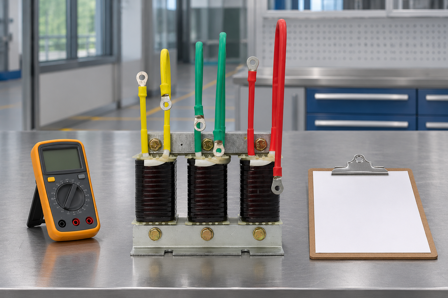
Use a test matrix that distinguishes coverage
This qualitative matrix can be incorporated into the commissioning plan. It provides no universal resistance, temperature, or delay limit. Establish those values from the actual device and panel design before testing. The acceptance column should identify a document revision or an approved project criterion so that another engineer can reproduce the decision later.
| Test scope | Evidence to record | What it can establish | What remains unproven |
|---|---|---|---|
| Identification and isolated inspection | Installed model, terminals, wire numbers and drawing revision | The test concerns the intended protection path | Sensor calibration and switching performance |
| Isolated contact-state check | Ambient condition, disconnected test boundary, measured state | Present electrical state of the identified contact | Temperature at which it changes state |
| Approved input or circuit simulation | Stimulus location, control response and final device state | Operation downstream of the simulation point | Any sensor or wiring bypassed by the simulation |
| Manufacturer-approved sensor verification | Method, reference temperature, transition and reset observations | Response under that specified test method | Conditions outside the verified range |
| Restoration and restart check | Temporary connections removed, settings restored, restart behavior | Correct return to the approved operating arrangement | Long-term thermal suitability under every load |
Check continuity without confusing parallel paths
An isolated continuity check should have a defined electrical boundary. A reading across a connected circuit can include controller inputs, suppression components, or parallel branches. Such a reading may not represent the thermal contact itself. The approved procedure should state which connections, if any, are separated for measurement and how they are identified and restored afterward.
Record the instrument, test mode, observed state, ambient condition, and comparison criterion. A continuity buzzer alone is a weak record because its operating threshold is instrument dependent. If the documentation calls for a normally closed contact and the isolated result is open at an ordinary ambient condition, investigate identification, wiring damage, device temperature, and the device condition before declaring a failed sensor. Do not bridge it to regain compensation while the cause remains unresolved.
Distinguish a contact check from calibration
Observing a closed contact at ambient temperature does not prove the operating setpoint. Verifying that setpoint requires an appropriate reference, a permitted method of applying temperature, and the device manufacturer’s acceptance criteria. Heating the assembled reactor with an uncontrolled heat gun or loading it until the protection trips is not a substitute for an approved test. It can damage insulation or expose personnel to energized parts.
Some temperature switches use differential thermal expansion to operate their contacts. The Federal University of Pará demonstration explains the bimetal principle. It provides physical background, not a statement about the internal sensor construction of every CKSG unit. Confirm the supplied protection type before choosing a calibration method; do not infer it from this educational example.
Test the downstream trip path deliberately
A functional test must specify where the stimulus enters the circuit. Simulating a controller input can prove controller logic and outputs while bypassing the field contact and its wiring. Opening a designated test point in an isolated control loop can cover a different boundary. Neither result should be reported as proof of a component excluded from the test. Use only the method and test facilities approved for the panel.
Record the command state before the stimulus, the indicated alarm, the change in switching command, and the observed state of the final device. Identify whether the design requires a contactor to drop out, a breaker to trip, an enable signal to be removed, or another specified action. Do not rewrite the design around a convenient existing indication. An illuminated alarm alone does not establish that capacitor current has been interrupted.
For a contactor-operated stage, the distinction between a control signal and reliable mechanical operation is particularly important. A weak coil supply can complicate the result. Use the separate capacitor contactor coil investigation when the final device moves abnormally during a steady command. Preserve the original event evidence instead of repeatedly issuing commands to a potentially damaged stage.
Verify reset and restart behavior
The protection device may return to its normal state after cooling, but the complete panel’s restart policy is a separate design decision. Determine whether the stage should remain inhibited until acknowledgement, wait for an approved delay, or rejoin an automatic sequence under defined conditions. Do not assume that a self-resetting contact authorizes immediate capacitor reconnection. The capacitor’s discharge requirements and the switching arrangement still apply.
Include loss and restoration of control power where the approved scope permits. Confirm what happens if an alarm is acknowledged while the thermal condition remains active. Verify that a manual operating mode cannot override a required protective inhibit. If the schematic does not define these cases, raise a design clarification rather than selecting an arbitrary field behavior. Document the accepted restart state in the final test record.
Investigate repeated trips without defeating protection
Repeated thermal operation can indicate excessive duty, inadequate cooling, a blocked airflow path, an unsuitable installation environment, a connection problem, or a protection-device fault. Establish the actual reactor current and operating condition using the approved measurement plan. Record capacitor-stage status and the relevant harmonic conditions so that a changing electrical duty is not mistaken for a purely ventilation-related problem.
Compare the installed reactor and capacitor with the approved matched combination. A reactor is not a generic interchangeable inductor chosen only by enclosure size. The capacitor and reactor matching guide explains the engineering relationship. Check the installed combination against its approved component documentation before applying the guidance. Do not raise a temperature threshold merely because a higher insulation class is printed elsewhere in the specification.
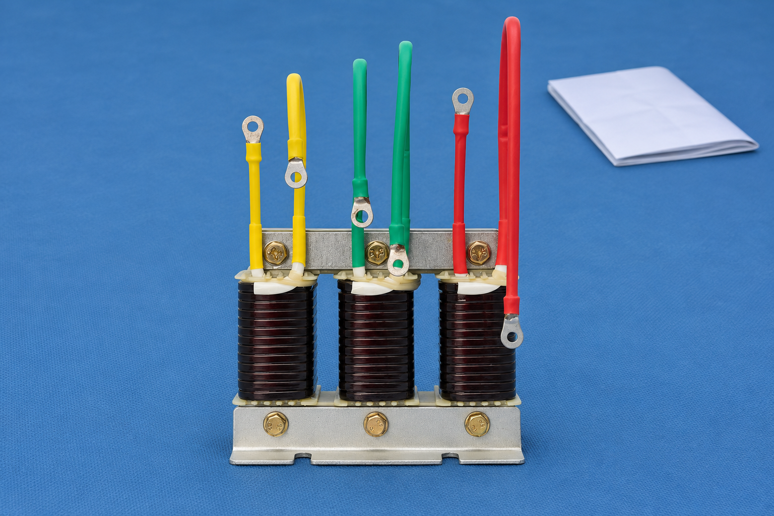
Close the test with a restoration record
Temporary test connections and separated conductors must be accounted for before release. Record the restored wire identification, terminal checks required by the manufacturer, normal protection state, controller mode, and the person approving return to service. Remove temporary inhibits according to the approved procedure. Update the drawing or defect register if the work identified an undocumented difference, even when no component was replaced.
Keep photographs and the completed matrix with the stage’s commissioning record. State which test boundaries were covered and which were not. If sensor calibration could not be performed, say so directly while documenting the downstream functional test separately. This gives maintenance staff a useful starting point when an alarm recurs and avoids turning a limited continuity reading into a claim about complete thermal protection performance.
Educational background: thermal expansion
Physics Demos’ bimetallic-strip lesson illustrates how different thermal expansion rates can produce mechanical movement. Use it to understand a possible temperature-switch mechanism, not as a method for heating or testing an installed reactor. The actual sensor type and test requirements must come from the delivered equipment documentation.
Frequently asked questions
Does a closed thermal contact prove the reactor is healthy?
No. It establishes only the measured contact state within the stated test boundary and conditions. Winding condition, cooling, electrical duty, sensor calibration, and the downstream protection response require their own evidence.
Can I use the insulation class as the trip temperature?
No. Insulation classification and a protection device’s operating setpoint describe different things. Use the installed device specification and approved design; do not derive a field setpoint from a general insulation-class temperature.
Is an alarm indication enough for a functional test?
No. Verify the required downstream action and identify the final element involved. An alarm can operate correctly while a wiring, logic, or switching-device problem prevents the stage from reaching its specified safe state.
Should an intermittent thermal contact be bypassed temporarily?
Do not bypass required protection to restore operation. Investigate the device, wiring, and actual temperature under the approved maintenance procedure. Keep the affected stage in its designated safe state until the cause and permitted remedy are established.