

IEEE 519 harmonic limits are a PCC-based design and verification framework for steady-state voltage and current distortion. Before an active power filter is sized, an engineer should define the user point of common coupling, identify whether voltage or current distortion is the decision issue, collect maximum-demand and short-circuit data, and obtain a representative harmonic record.
This is not a compliance promise for any product. It is a practical way to turn a vague requirement—“meet IEEE 519”—into a measurable scope for the utility, plant team, consultant, and mitigation supplier.
Contents
- Part 1: scope of IEEE 519
- Part 2: PCC definition and location
- Part 3: voltage THD versus current TDD
- Part 4: Isc/IL and current-distortion rows
- Part 5: measurement record before sizing
- Part 6: translating data into mitigation scope
- Part 7: RFQ inputs and Fit Boundary

Part 1. What do IEEE 519 harmonic limits govern?
IEEE 519 establishes harmonic-control design goals for electrical systems containing linear and nonlinear loads. The IEEE Standards Association describes the interface between sources and loads as the point of common coupling and states that the standard addresses steady-state limitations. That boundary matters: an instantaneous event, a drive-terminal reading, and a user PCC result are not interchangeable measurements.
For an industrial facility, the standard helps separate two responsibilities. The user controls harmonic-current injection from nonlinear loads. The supply system’s voltage-distortion condition is assessed at the same interface. A successful project therefore needs source information and load information, rather than only a filter catalog or a target percentage copied from another plant.
| Question | IEEE 519-oriented answer | Procurement implication |
|---|---|---|
| Where are goals evaluated? | At the defined user PCC | Put PCC on the one-line before comparing data |
| Does it cover transient events? | The stated scope is steady-state distortion | Keep event and flicker studies separate |
| Are current and voltage checked the same way? | No; they use different quantities and limits | Request both voltage and current records |
| Does a standard select a device? | No; it sets a data-based design objective | Create an engineering scope before specifying APF capacity |
The standard should be read together with project requirements, utility rules, applicable grid codes, and the plant’s own protection/design criteria. It does not certify a supplier’s equipment or eliminate the need for commissioning evidence.
Part 2. Where should engineers define and measure the PCC?
The PCC is commonly the electrical point closest to the user where the system owner or operator could offer service to another user. ABB’s IEEE 519 review notes that, for a manufacturing plant served through a dedicated transformer, this is often the high-voltage side of that transformer; the actual location must be confirmed from the system arrangement.
Internal measurements remain valuable. A drive feeder reveals the source spectrum. An MCC shows aggregation of several loads. A transformer secondary can show whether the bus is affected. None of those automatically becomes the PCC used for a project requirement.
| Location | Best use | What it cannot establish alone |
|---|---|---|
| Individual nonlinear-load feeder | Source diagnosis | Full plant current injection |
| MCC / process board | Aggregated process load | Utility/PCC performance |
| Transformer secondary | Plant-bus condition | PCC without confirmed ownership/interface context |
| Defined PCC | Standards-based assessment | Local source identification without supporting feeder data |
Important: Do not substitute a convenient panel meter location for the PCC. IEEE 519’s scope is the source/load interface identified for the installation (IEEE 519-2022).
Part 3. Why are voltage THD and current TDD different checks?
Voltage total harmonic distortion describes distortion of the voltage waveform. Current total demand distortion (TDD) expresses harmonic current against maximum demand load current. Current THD, often shown as THDi, uses the instantaneous fundamental current as its denominator. This means a light-load THDi value can appear high without describing the same current-distortion assessment used for IEEE 519.
The Mirus technical paper states that current THD should not be used as the current-compliance denominator; TDD is tied to demand current. A team can use current THD for troubleshooting, but it should not turn an instantaneous light-load screen into an APF capacity specification.
| Quantity | Denominator | Practical role |
|---|---|---|
| Voltage THD | Fundamental voltage | Measures voltage waveform distortion at the relevant point |
| Current THDi | Instantaneous fundamental current | Useful for live source/load diagnosis |
| Current TDD | Maximum demand load current, IL | Used for IEEE 519 current-distortion assessment |
| Individual harmonic current | IL for the limit context | Shows which orders dominate the requirement |
From the field: Engineers frequently ask how to distinguish “THD, thd, TDD” and how maximum demand current is obtained (Schneider Electric community discussion). The question identifies a data requirement; it does not prove a site’s limit or device capacity.
Part 4. How does Isc/IL affect the current-distortion assessment?
Isc is the available short-circuit current at the PCC. IL is the maximum demand fundamental load current at that same PCC. Their relationship, Isc/IL, selects the applicable current-distortion category. It is not valid to combine fault data from an upstream source with demand current measured at an unrelated downstream panel.
The TCI and IEEE educational materials explain that current harmonic limits are expressed against the source-strength relationship. A weak and a strong source can therefore have different allowable current-distortion context even when a plant uses similar nonlinear equipment.
| Required input | Who commonly supplies it | Review point |
|---|---|---|
| Available short-circuit current, Isc | Utility, system study, consulting engineer | Must correspond to the PCC |
| Maximum demand current, IL | Revenue data, study, or representative logging | Record method and operating period |
| Voltage class | One-line and supply documentation | Use the PCC voltage, not drive output voltage |
| Harmonic spectrum | Power-quality analyzer | Capture individual orders and operating state |
| Existing PFC/filter data | Plant electrical team | Check for background resonance or changed impedance |
Do not guess Isc/IL from transformer nameplate alone. A system study or supply-side data may be required.
Part 5. Which measurement record should precede APF sizing?
An APF scope needs a time-aligned measurement record, not just the largest THDi screenshot. Capture voltage, phase current, harmonic orders, kW, kVA, PF, load state, capacitor switching, and relevant transformer or generator operating mode. The record should include the period that represents high nonlinear-load duty.
| Record item | Why it matters before sizing |
|---|---|
| Defined PCC and one-line diagram | Keeps source, load, and metric locations consistent |
| Voltage THD trend | Identifies whether voltage distortion needs separate review |
| Harmonic-current spectrum | Reveals dominant orders and changing load patterns |
| IL method and maximum-demand record | Allows current TDD assessment |
| Isc source and date | Determines source-strength category |
| Existing capacitors and reactors | Flags resonance and retrofit constraints |
| Expansion/load-change plan | Avoids sizing only for a temporary operating point |
For drive-heavy installations, the companion VFD harmonics selection guide explains how feeder measurements complement, rather than replace, PCC data.

Part 6. How should results become a mitigation scope?
Translate the standard review into a clear engineering problem statement. If the issue is harmonic-current injection at a reviewed bus, an active harmonic filter can be evaluated. If the issue is dynamic reactive demand, an SVG assessment is separate. If existing capacitors interact with nonlinear loads, resonance and detuning need their own review.
| Evidence from study | Next engineering step | Do not assume |
|---|---|---|
| Current distortion objective at a defined bus | Evaluate APF topology, capacity, and CT placement | That SVG alone removes harmonic current |
| Fast kvar variation with limited harmonic-current issue | Evaluate SVG / var-support approach | That capacitors respond correctly to all dynamics |
| Capacitor alarms and harmonic magnification | Review detuning, impedance, and protection | That replacing fuses solves the cause |
| PCC target not yet defined | Obtain utility/system-study inputs | That a drive-terminal THD number proves compliance |
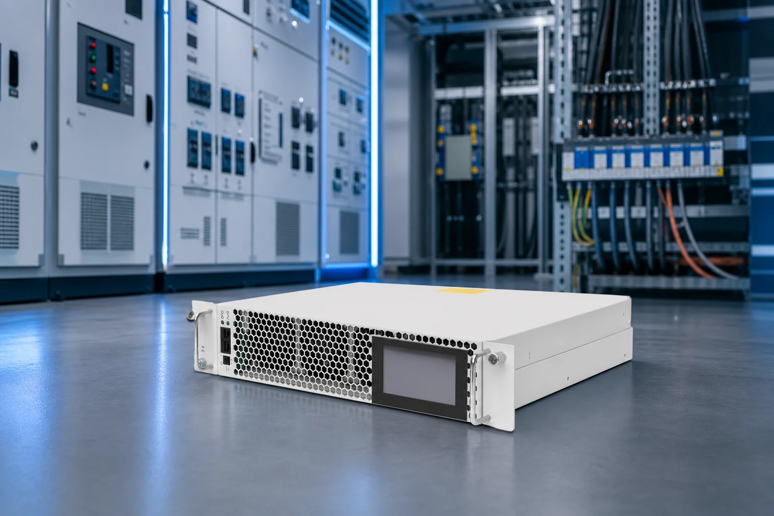
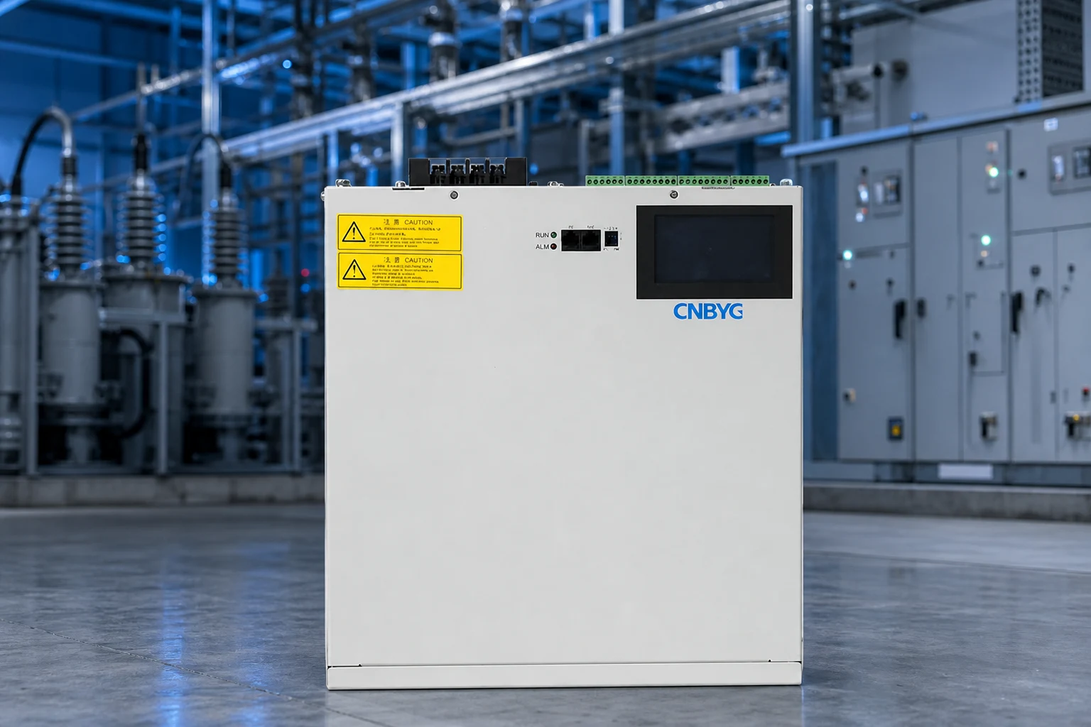
CNBYG’s Power Quality System and AHF Active Harmonic Filter pages provide product-line context. They do not guarantee IEEE 519 compliance; final selection requires the project’s PCC data, topology, and commissioning plan.
Part 7. What should a standards-aware RFQ include, and when is CNBYG not a fit?
| Buyer should provide | Why it matters | Common mistake |
|---|---|---|
| One-line with PCC marked | Aligns measurements and requirements | Calling every panel the PCC |
| Utility/source fault information | Establishes Isc input | Using a transformer kVA estimate as Isc |
| Maximum demand-current method | Establishes IL for TDD | Using light-load current |
| Meter logs and spectrum | Shows time and harmonic-order behavior | Submitting one screen capture |
| Voltage class and existing filters | Identifies system context | Omitting capacitor/reactor details |
| Target standard and owner requirement | Defines acceptance language | Asking for “IEEE compliant” without scope |
| CT, protection, enclosure, and communications | Makes an APF installation reviewable | Leaving integration to site installation |
Fit Boundary: This guide is for teams preparing harmonic data and a standards-aware engineering scope. It is not a legal interpretation of IEEE 519, a utility acceptance letter, a grid-code review, or a guarantee that an APF will meet a project target. Send a defined data package through the CNBYG contact page for product-fit discussion.
FAQ
What are IEEE 519 harmonic limits?
They are steady-state harmonic-control design goals for voltage and current distortion at the defined user PCC.
Where is the PCC for IEEE 519?
It is the defined source/load interface for the installation, commonly established from the supply arrangement and ownership context.
What is the difference between THD and TDD?
THD uses the fundamental quantity at the measurement moment. Current TDD references maximum demand load current, IL.
How is TDD calculated?
TDD is harmonic current expressed as a percentage of the applicable maximum demand load current at the PCC.
What does Isc/IL mean?
It compares available short-circuit current to maximum demand load current at the PCC and is used for current-distortion category selection.
Does IEEE 519 apply to voltage and current?
Yes. It includes separate steady-state distortion goals for voltage and current at the PCC.
How long should harmonic measurements be logged?
Long enough to capture representative maximum-demand and nonlinear-load operating conditions; define the period with the project team and measurement method.
Can an APF guarantee compliance?
No. An APF is evaluated against the measured system, project target, topology, source condition, and commissioning result.