Intelligent Capacitor Communication Faults: A Structured RS485 Check
An intelligent capacitor communication fault should be investigated separately from a capacitor switching or electrical-protection fault. First identify which units remain visible, whether local control is healthy, and what changed before the fault. Then verify the documented network arrangement, connector type, device roles, and supported protocol. RS485 describes an electrical interface; its presence does not establish Modbus compatibility or permission to connect a generic computer adapter. Preserve the original configuration and isolate equipment under the approved procedure before disturbing connectors or measurement circuits.
Define what has stopped communicating
Describe the symptom precisely. A controller that cannot discover any modules presents a different investigation from one missing unit, a disconnected group in another cabinet, or intermittent status during switching. Record the unit identities, locations, visible indications, and the time of the event. Do not assume that a dark communication indicator has the same meaning across different product families or firmware versions.
Identify which functions depend on the communication link. Local indication, coordinated stage control, an external status display, and a supervisory-system connection may use different paths. The installed instructions should define the permitted behavior following a communication loss. Do not claim that a healthy local display proves the complete panel remains correctly coordinated, or that loss of remote visibility necessarily means the capacitor itself has failed electrically.
Establish the product and protocol boundary
CNBYG’s BY81 intelligent capacitor page describes modular combinations and lists RS485 online connection accessories for adjacent units, cabinet levels, and connections between assemblies. Use the delivered manual and actual system drawing to confirm which accessories and connection arrangements apply. Do not infer a connector pinout, supported protocol, or universal network capacity from the physical appearance of a socket.
The Texas Instruments RS485 design guide explains that RS485 specifies electrical driver and receiver characteristics rather than a complete messaging protocol. It also discusses bus topology, termination, and signal integrity. Those principles explain why cable arrangement matters, but they do not replace the BY81 network instructions. A product’s internal coordination bus should not be treated as an open external interface without written documentation.
This distinction prevents a common diagnostic mistake: attaching an unsupported polling tool and interpreting silence as a failed device. A test tool can have the wrong protocol or bus role even when its connector and voltage interface appear compatible. Obtain the permitted diagnostic method and read-only access conditions from the equipment documentation before adding another transmitting device.
Save a baseline before changing anything
Capture the system topology, module locations, displayed identities, controller mode, relevant settings, and firmware or hardware revisions where available. Photograph connector positions and cable labels while following the site’s safety procedure. Record whether the fault began after a replacement, enclosure alteration, cable extension, firmware change, or maintenance visit. A recent change helps select a test; it does not automatically establish the cause.
Keep original settings exports and photographs unchanged. Record diagnostic changes in a separate log with the time, person, expected result, and observed result. Changing an address, replacing a cable, and restarting the controller at the same time can restore service while leaving the cause unknown. Prefer a controlled comparison that isolates one approved change and preserves a route back to the accepted configuration.
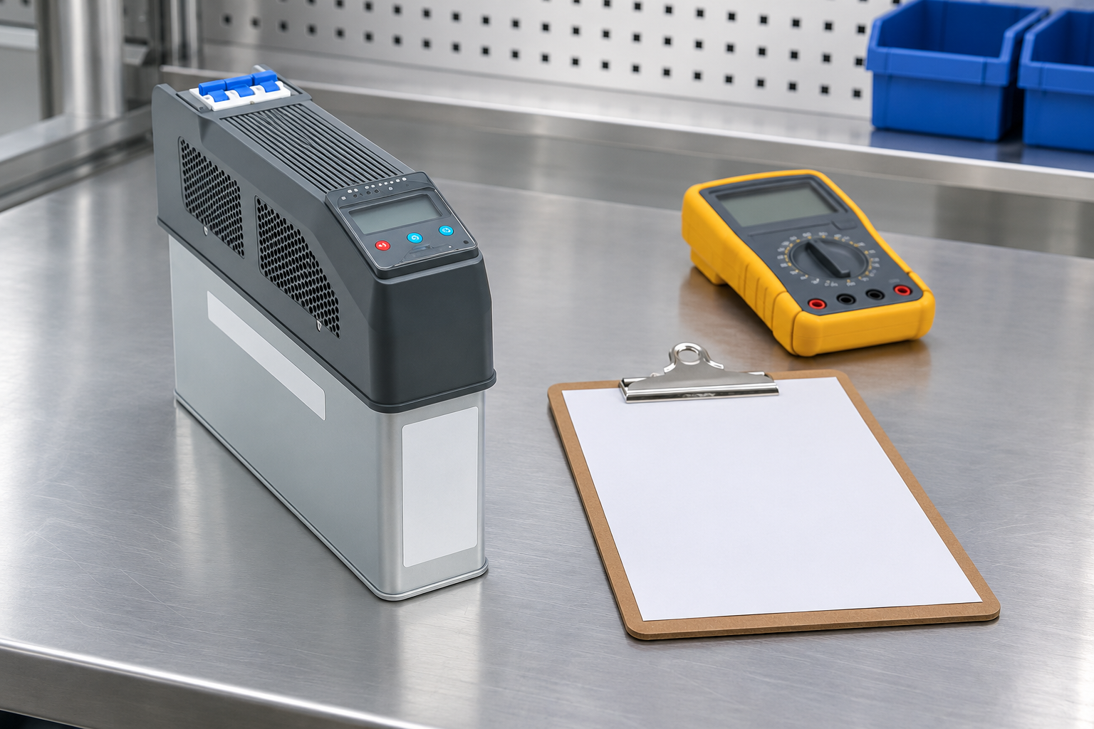
Use the fault pattern to choose a boundary
This table organizes evidence collection without prescribing a product-specific fault code. It contains hypotheses, not automatic diagnoses. Confirm every indicator meaning and permitted test action from the installed manual. In particular, do not disconnect an operating network segment simply because a general troubleshooting table suggests the segment might be involved.
| Observed pattern | Boundary to investigate | Evidence that helps | Avoid assuming |
|---|---|---|---|
| No units visible from the intended controller | Controller role, supply, connection and protocol | Local controller status, approved network drawing, recent changes | Every capacitor module has failed |
| One unit absent while adjacent units remain visible | Unit identity, local condition and its connection | Exact unit indication, connector record and configuration | The electrical capacitor element is defective |
| A whole downstream group disappears | Shared cable section, connector or group supply | Physical topology and the first missing boundary | A software setting is necessarily responsible |
| Communication is intermittent during switching | Timing, cable route, supply disturbance and interference | Event times compared with switching commands | Any single nearby power cable proves interference |
| Fault follows a module replacement | Compatibility, role selection and approved configuration | Original and replacement model and revision comparison | Similar housings establish interchangeability |
| Local control remains available but remote status fails | Supervisory interface or external path | Separate local and remote observations | The internal coordination bus and external interface are identical |
Inspect connections with the correct safety boundary
Prepare the isolation procedure before touching connectors inside a compensation panel. A communication connector may be physically close to energized power terminals, and auxiliary supplies can remain active when another disconnect is open. Include stored capacitor energy and remote command sources in the work boundary. A small plug is not evidence that the surrounding work is safe.
OSHA 1910.333 addresses deenergization, verification, and electrical work practices within its scope. Apply the site’s governing rules and equipment instructions. Do not unplug a module, remove a CT connection, or perform a resistance test on an energized circuit as a general communication check. Where live monitoring is required, use the approved method and qualified personnel rather than creating an improvised access point.
During the isolated inspection, compare the cable type, connector orientation, locking condition, and routing with the accepted arrangement. Look for damaged latches, crushed cable, strain at a plug, corrosion, contamination, or evidence that an accessory has been substituted. Record the defect before disturbing it. Do not assume a standard-looking data cable has the same pin assignment or construction as the specified online connector.
Review topology without adding arbitrary components
Draw the actual connection path, including cabinets, interconnecting cables, branches, and accessories. Compare it with the manufacturer’s permitted arrangement. A drawing that shows only logical module order may conceal a long physical branch or an unapproved connection between cabinets. Preserve the physical routing information when investigating an intermittent problem so that a subsequent technician can inspect the same boundary.
Do not add termination, bias resistors, shielding changes, or a ground connection simply because they appear in a generic RS485 example. The installed equipment may already provide relevant interface components or may use a specified accessory arrangement. First identify what is present and what the equipment instructions require. A change intended to improve one link can alter the loading or reference conditions of the whole network.
Verify identities and control roles against the manual
Some modular systems select roles automatically; others use configured identities or a defined external controller. Determine the actual arrangement before searching for a duplicate-address parameter that may not apply. Record the expected role and the role observed at each relevant unit. A replacement unit may require a documented commissioning action even when the original system formed its network automatically.
If manual addressing or communication parameters are supported, compare the installed configuration with the approved record. Avoid guessing baud rate, parity, node number, or master selection from another manufacturer’s example. Do not write a discovered parameter merely to make a diagnostic program receive a reply. Restore or approve every change explicitly, and verify coordinated operation through the actual intended controller afterward.
Separate switching disturbances from communication causes
Intermittent failures deserve a timeline. Compare the fault with stage commands, source changes, control-power interruptions, cabinet temperature, and maintenance activity. Use observations from the same time basis where possible. A fault appearing near a switching event justifies investigation of the event; it does not prove that electrical interference is the sole cause. An inadequate auxiliary supply or a loose connection may create a similar pattern.
Investigate the complete equipment behavior, including any protective inhibit or local fault indication. Use the intelligent capacitor versus conventional bank guide to understand the different control arrangements, and the intelligent-capacitor status indication article for the role of visibility in maintenance. Neither general guide replaces the installed unit’s fault-code definitions.
Verify recovery at the complete-system level
After an approved repair, confirm that every intended unit is visible, correctly identified, and associated with the expected location or function. Check that fault indications have the meaning stated in the manual and that no temporary configuration remains. Then verify the permitted coordinated stage response under the commissioning plan. A successful reply from one diagnostic tool does not establish correct automatic compensation.
Include the operating condition that originally accompanied the fault where it can be tested within the approved scope. If the original event cannot be reproduced, record that limitation rather than declaring the intermittent issue eliminated. Preserve the replaced cable or module identification, the accepted configuration, and the final topology. Use the automatic capacitor bank operating guide for the surrounding control sequence and protection context.
Prepare an escalation package that can be acted on
Send the supplier the exact product and controller identities, relevant revisions, the approved network drawing, clear photographs, the fault pattern, and a timed record of the tests already performed. Distinguish confirmed observations from hypotheses. Include whether the fault affects one unit, a group, or the whole system and whether local operation differs from supervisory visibility. Do not include passwords or unrelated network credentials in a general support document.
Ask for a specific next diagnostic step and its permitted conditions. If an interface is proprietary or undocumented, request the appropriate service procedure rather than continuing to transmit guessed messages. Keep any limitation on operation visible in the maintenance record until the equipment is released. This makes the investigation useful even when a replacement part must be obtained or a vendor-specific tool is required.
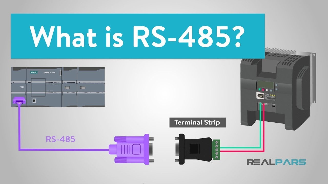
Educational background: the RS485 electrical interface
RealPars’ lesson explains RS485 in industrial control systems. It helps distinguish an electrical interface from the higher-level behavior of a complete network. The lesson is educational material from an automation training publisher, not a declaration that the BY81 internal network accepts a particular open protocol or generic polling tool.
Frequently asked questions
Does an RS485 connector mean the capacitor uses Modbus?
No. RS485 specifies electrical signaling characteristics. Confirm the supported protocol, connection role, pinout, and permitted diagnostic method from the delivered equipment documentation before connecting another device.
Can local operation continue when communication is lost?
That depends on the installed system and its documented fault behavior. Verify local protection, coordination, and operating restrictions separately. Do not infer the permitted operating state from a healthy display alone.
Should I add a termination resistor to stop intermittent faults?
Only after confirming the actual topology, existing interface components, and manufacturer requirements. An arbitrary resistor can change the network loading and does not establish that termination caused the fault.
Is a replacement module ready as soon as it appears online?
No. Verify compatibility, identity, control role, settings, protection indications, and coordinated stage operation under the approved commissioning plan. Retain the final configuration and any unresolved restrictions in the maintenance record.