Reactive Power Compensation in Mining Operations
Mining reactive power compensation starts with a survey of motor feeders, operating cycles and supply strength, rather than a capacitor rating selected from transformer capacity. Measure active power, reactive power, displacement power factor and waveform distortion during representative mining operations. Then determine whether the main requirement is steady fundamental reactive correction, fast changing demand, harmonic mitigation or a combination. A mine with long feeders and an alternative generator supply also needs a location and coordination study. Equipment selected for one switchboard must not be assumed suitable for every underground, surface or standby operating condition.
Turn the mining process into an electrical test plan
Begin with the actual distribution drawing and a list of operating equipment. Crushers, conveyors, ventilation fans, pumps and hoists can have very different duty patterns. Identify direct-connected motors, controlled drives and existing correction equipment separately. Obtain the equipment documentation before assigning an electrical characteristic to a machine simply because it is used in mining.
Build the survey around process events. Record when a conveyor train starts, a crusher changes feed, a pump switches duty, or a major production section stops. Include the remaining ventilation and drainage loads during a production shutdown. An apparently quiet shift can still be electrically important because a large fixed capacitor stage may remain energised while active power falls.
For every record, identify the supply configuration. Normal utility supply, a different transformer arrangement and an approved generator-backed condition should have separate labels. Do not combine their measurements into one unexplained average. The network impedance and permitted load combination can change between configurations, affecting the compensation assessment.
A useful research starting point is the University of Pretoria repository, which includes work on reactive power and harmonic compensation in the coal-mining industry. Such case studies establish that the two problems can occur together; they do not supply a universal equipment rating for another mine.
Distinguish reactive demand from waveform distortion
A low displayed power factor does not by itself identify the remedy. Displacement power factor describes the fundamental-frequency voltage-current relationship. True power factor expresses active power relative to apparent power and can also reflect nonsinusoidal current. A capacitor intended to offset fundamental reactive demand is not a general means of removing harmonic current from a drive feeder.
Retain the meter’s definitions, phase association, current-sensor settings and reactive-power sign convention. Two exported columns labelled PF may represent different quantities. Before comparing them, verify what each instrument reports and whether the measurement points enclose the same loads. An incorrect current-sensor association can undermine an otherwise detailed survey.
Use IEEE 1459-2025 as a reference for electrical-power definitions under sinusoidal, nonsinusoidal, balanced and unbalanced conditions. The project report should state which quantities it uses. Keep the billing objective, internal feeder-current objective and waveform-distortion objective visible as separate acceptance questions.
The existing displacement versus distortion power-factor logging guide helps organise these records. It complements this mining survey by explaining the quantities rather than selecting equipment for a particular production process.
Survey the states that determine the design
| Mining operating state | Records to collect | Decision supported |
|---|---|---|
| Steady conveyor and ventilation operation | Active and reactive power, voltage, current and enabled correction stages | Establish the sustained fundamental correction requirement |
| Crusher feed changes | Time-aligned power trend and process notes | Determine whether changing demand exceeds the existing control response |
| Hoist or intermittent equipment cycle | Repeated cycle records and relevant voltage events | Separate recurring demand changes from isolated disturbances |
| Production shutdown with essential loads | Remaining active power, reactive-power sign and bank status | Check for excessive correction at reduced load |
| Drive-heavy operating combination | Current spectrum, voltage distortion and displacement factor | Identify whether a separate harmonic investigation is necessary |
| Permitted generator operation | Generator documentation, load list and compensation state | Establish a source-specific operating arrangement |
These are qualitative survey tasks, not universal switching instructions. The responsible site engineer must select safe measurement locations and operating tests. The survey should not require bypassing production interlocks or accessing energised terminals without the appropriate procedures and qualifications.
Capture enough repeated operation to distinguish a characteristic cycle from an unusual event. Record the sampling and aggregation intervals, instrument clock alignment and missing periods. A short trend showing one favourable interval is weak evidence for a mine that operates across several shifts and load combinations.
Estimate correction without hiding the assumptions
For a balanced sinusoidal operating state, an initial calculation is Qc = P × (tan φ1 − tan φ2). Here P is active power in kW, Qc is the estimated fundamental reactive correction in kvar, and the angles correspond to initial and target displacement power factors. State these assumptions next to the calculation.
As a teaching example, consider an invented 300 kW load changing from a displacement factor of 0.80 to 0.95. The corresponding tangent values are 0.75 and approximately 0.329. The estimated correction is 300 × (0.75 − 0.329), approximately 126 kvar. This example is not a measured mine result, a product rating or a purchase recommendation.
Repeat the calculation for representative low, normal and high production states. Preserve sign and account for compensation already operating at the measurement boundary. If the survey measures the net demand with a working bank enabled, clarify whether the new equipment is supplementing that bank or replacing it. Otherwise the same correction may be counted twice.
A calculation at maximum load does not determine the smallest suitable stage or the acceptable light-load behaviour. Check what happens when an associated motor stops and what remains connected during the shutdown state. Use the recorded demand range and approved network study to develop the final arrangement.
Choose a compensation location deliberately
Compensation near a motor, on a section board and at the utility interface can address different objectives. Local correction can reduce reactive current in the upstream feeder serving that load, while central correction may primarily change the quantity at a broader measurement boundary. Identify the intended benefit before comparing quotations.
Long mine feeders require particular attention to the actual voltage and impedance conditions. Do not promise that improving power factor will resolve every voltage problem. Conductor impedance, load starting, control behaviour and source conditions may need separate investigation. Retain the voltage measurements alongside the reactive-power trend so that the design addresses observed behaviour.
Draw the current-sensor locations and control boundaries. Where several correction devices exist, explain which loads each device sees and how their control responsibilities are coordinated. A controller responding to a signal that includes another uncontrolled compensation device can make commissioning difficult. Record approved settings and ownership of subsequent changes.
Compare capacitor stages and dynamic correction
A fixed capacitor arrangement can be appropriate for a stable, coordinated task, but suitability depends on switching, voltage, discharge requirements and the associated load. It should not remain enabled merely because the original drawing shows a continuous-duty motor. Confirm the current operating practice and condition of the installed equipment.
A stepped bank provides discrete changes in correction. Review stage size, controller measurement, switching frequency and the actual demand cycle. Repeated switching deserves a diagnosis of both load behaviour and configuration. Adding stages or extending delays without that diagnosis can conceal the underlying mismatch.
An SVG can be considered when the required correction range and response justify dynamic equipment. Verify the proposed model’s voltage, current or kvar basis, operating range, thermal conditions and documented functions. A generic SVG name does not prove harmonic filtering, unbalance correction, generator compatibility or suitability for a hazardous location.
The CNBYG SVG product page is a starting point for an enquiry based on measured requirements. Send the actual feeder records for model-specific assessment. The separate dynamic-load SVG sizing guide discusses operating range and response requirements.
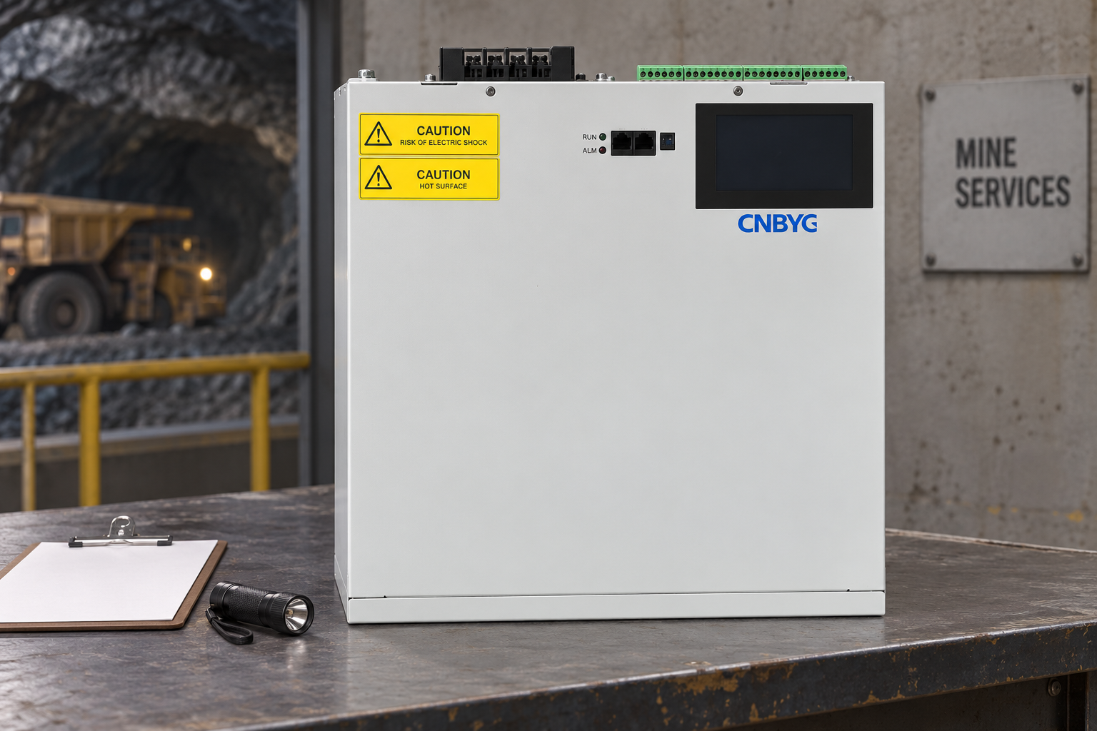
This product-reference illustration shows the enclosure exterior only. It does not demonstrate underground approval, hazardous-area certification, a completed installation or a correction rating. Use actual equipment labels, documentation and site requirements when selecting the installation location.
Check harmonics before changing a capacitor bank
Review existing drive inputs, capacitor stages and any detuning reactors. The network and capacitors interact, so a change in capacity or supply configuration can alter resonance conditions. A mine with substantial nonlinear loads needs an assessment that includes voltage distortion and the current spectrum at clearly identified locations.
The IEEE 519-2022 standard page provides the scope for harmonic control at the supply interface. Apply the relevant criteria at the correct boundary. A high harmonic percentage measured on a small internal feeder is not automatically the same as a supply-interface compliance failure.
Do not prescribe a reactor percentage or harmonic-filter rating from the industry name alone. The equipment design depends on network conditions, existing banks and measured loads. If harmonic mitigation is required, write it as a separate verified requirement alongside fundamental reactive correction, with clear responsibilities for studying interactions.
For a narrower drive-feeder investigation, use the mining conveyor VFD harmonics measurement guide. Its feeder test plan complements the mine-wide reactive-power survey without assigning the same task to both pages.
Define acceptance and the handover package
Before purchase, agree the test states, instrument definitions, measurement locations and operating restrictions. Compare like-for-like production conditions before and after commissioning. Retain raw exports and explain any difference in throughput, enabled machinery or source arrangement that could influence the comparison.
Check reduced production and approved alternative supply as well as normal output. Record power quantities, voltage, distortion, correction status and relevant alarms. A commissioning pass under utility supply does not automatically establish satisfactory operation on generators. Any untested condition should remain explicitly outside the verified acceptance result.
The handover should include the final drawing, settings, equipment documentation, baseline and acceptance records, maintenance responsibilities and the conditions that trigger reassessment. New drives, transformer changes or altered production duty should prompt review. Financial claims require the actual tariff and billing evidence; improved power factor is not proof of an equal reduction in process energy consumption.
Further learning: measurement and acceptance boundaries
The NPTEL IIT Delhi lecture on power-quality standards and monitoring explains general measurement concepts useful for a mining survey. It is educational background and does not endorse a product or replace site engineering.
Watch Power Quality: Standards and Monitoring
Frequently asked questions
Can transformer capacity determine mining compensation size?
No. Use measured reactive demand across operating states, the existing compensation arrangement and network conditions. Transformer capacity provides context but does not identify the required correction profile.
Will capacitors remove drive harmonics?
Ordinary capacitors are not a general harmonic-removal device. Separate fundamental reactive demand from waveform distortion and assess capacitor-network interaction before making changes.
Can the same settings be used on generator supply?
Do not assume so. Assess the permitted generator configuration, documented equipment compatibility and relevant load states, and retain that arrangement in the acceptance and operating records.
What information belongs in a mining compensation enquiry?
Provide the distribution drawing, time-aligned P and Q records, instrument definitions, process-state notes, harmonic evidence, existing bank details, supply configurations, installation conditions and acceptance requirements.