Negative Power Factor: Meaning and Troubleshooting
Negative Power Factor: Meaning and Troubleshooting
Negative power factor usually means the meter sees power flow or phase direction opposite to its configured reference. It can appear during export, regeneration, a reversed CT, an incorrect phase sequence, a sign-convention mismatch or a very low active-power condition where small measurement errors dominate. It is not automatically a failed compensator and it should not be corrected by blindly increasing capacitors or SVG output.
The CNBYG SVG product page provides product context for reactive-current control. Troubleshooting must begin with the meter boundary, CT polarity, voltage reference, import/export direction and the definition used by the utility or plant controller.
What the sign can represent
Power factor is often displayed as a magnitude plus a leading/lagging or import/export sign. Some instruments display negative PF when active power is exported. Others use a sign for reverse current or leading reactive power. A generator, solar inverter, battery or regenerative drive can legitimately send active power back toward the source.
At very low kW, a small phase or offset error can also make the sign jump. Record kW, kvar, voltage, current, frequency, true PF, displacement PF and the meter’s sign convention before interpreting the number.
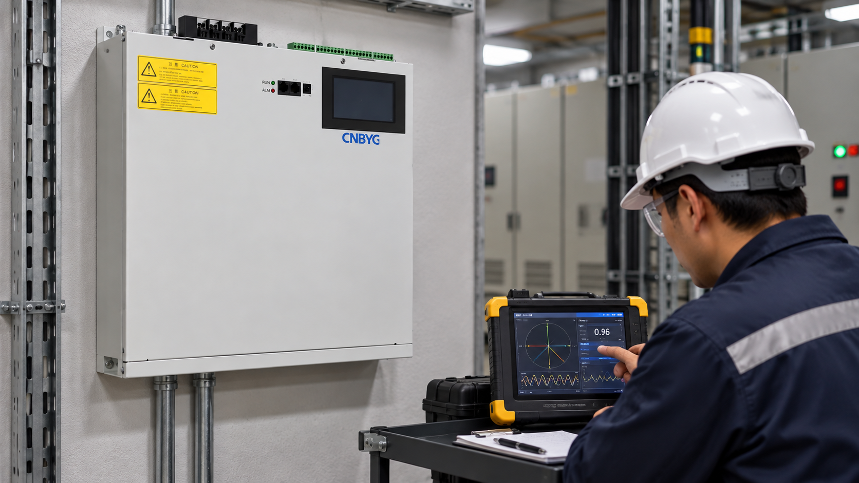
Troubleshooting table
| Observation | Likely cause | First check |
|---|---|---|
| Negative PF only during solar export | Active power direction is reversed by design. | Confirm PCC import/export convention and inverter state. |
| Negative PF after CT replacement | CT polarity, phase or ratio is wrong. | Compare current direction and marked CT wiring. |
| Sign changes at very low kW | Offset, noise or small net active power. | Check kW magnitude, averaging and analyzer agreement. |
| PF sign differs between meters | Different boundaries or sign settings. | Compare phase sequence, voltage reference and configuration. |
| Leading PF with capacitors on | Capacitive kvar exceeds inductive demand. | Record signed kvar and stage state at light load. |
| Negative reading during regeneration | Drive or machine exports active power. | Check four-quadrant operation and source direction. |
Verify CTs and phase references
Mark the CT arrow direction, phase labels, ratio, burden and shorting arrangement on the one-line diagram. Confirm the voltage leads use the same phase order. Compare the meter with an independent analyzer at the same point during a known import load. If the plant can export, test both directions with an approved procedure.
The SVG reactive-current compensation guide explains why a reversed CT or boundary mismatch can make a correctly operating SVG appear to have the wrong sign. Do not change the target until the measurement chain is proven.
Separate active and reactive signs
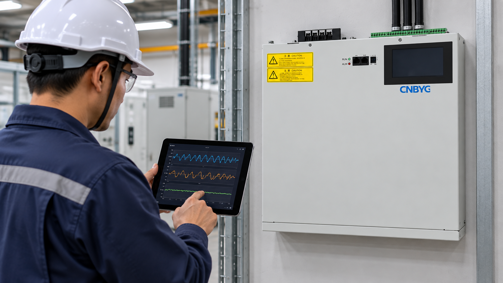
Plot signed kW and signed kvar together. A negative kW with positive or negative kvar may be normal for a generator, solar inverter or regenerative drive. A positive kW with unexpected leading kvar may indicate capacitors, cables or a control setting. A sign on PF alone is not enough to identify which component changed.
Use the same time base for source meter, feeder meter, inverter, SVG and independent analyzer. A bill may use import energy while a local analyzer shows instantaneous export. The grid-voltage and SVG capacity guide is useful when a voltage change also alters the converter current needed for kvar.
Check operating modes
List utility import, solar export, generator islanding, battery charge, battery discharge, motor regeneration, capacitor stages and SVG control. For each mode, state the expected kW sign, kvar sign, PF definition, CT boundary and controller hierarchy. This prevents an export sign from being treated as an alarm or an idle leading condition from being hidden.
If an APFC relay and SVG share a CT, define the primary controller, deadband, delay, leading limit and fallback. The SVG installation requirements guide covers safe access and cooling. The SVG commissioning checklist can record phase checks, mode changes and alarms.
Practical troubleshooting sequence
- Save the meter screenshot, configuration and timestamp.
- Record signed kW, kvar, voltage, current, frequency and both PF definitions.
- Mark the meter and CT boundary on the one-line diagram.
- Verify CT ratio, arrow direction, phase and voltage reference.
- Compare with an independent analyzer at the same boundary.
- Test known import and export states when safe and approved.
- Check capacitors, SVG, inverter, generator and regeneration modes.
- Review sign, averaging, multiplier and tariff settings.
- Change one setting at a time and keep a rollback value.
- Repeat light, normal, peak and transition tests.
Common mistakes
Do not call every negative PF a wiring fault. Do not correct reverse active power with capacitors. Do not ignore CT polarity after maintenance. Do not compare a feeder and PCC sign without reconciling the boundary. Do not tune an SVG before verifying the voltage reference. Do not round a near-zero kW value and then infer a stable negative PF.
Keep negative readings in the record even when they are expected. A documented export mode is evidence of correct configuration. An unexplained sign change is a measurement or coordination issue until proven otherwise.
Build a sign-convention record
Write the expected direction for active power and reactive power beside each meter. Include the CT arrow, phase labels, voltage reference, import/export state and whether leading or lagging is positive in that device. A short screenshot is not enough because the same display can use different signs in utility, generator and export modes.
During a known import test, record the source and feeder values with the correction disabled. During an approved export or regeneration test, record the same values with the source direction marked. If the expected sign does not appear, stop at the measurement check. Do not alter the SVG target, capacitor stages or inverter VAR mode until the reference is corrected.
For a near-zero kW case, use a longer synchronized trend and report the magnitude as well as the sign. Noise, offset and small CT errors can make PF alternate positive and negative without any real operating change. After wiring or firmware work, repeat the phase and polarity checks and preserve the as-left configuration with the acceptance record.
If a negative sign is expected during export, add an alarm only for an unexpected direction, not for the sign itself. If the sign changes with a capacitor stage while kW remains positive, investigate leading kvar and controller coordination. If the sign changes with no device or load change, repeat the independent analyzer check before reopening the equipment.
Keep the expected sign table with the controller settings. It should say whether import, export, regeneration, battery charge and battery discharge are normal for the meter. This prevents an operator from resetting a healthy export event or changing a correction target to hide a wiring problem. Recheck the table after a firmware, CT or transfer-sequence change.
The final troubleshooting note should identify the observed sign, expected sign, meter configuration, independent measurement, operating mode and corrective action. If the sign was expected, close it as an operating condition; if not, leave the wiring or configuration issue open until the repeat test passes.
Do not use a negative PF label as a substitute for signed kW and kvar. Those two quantities show whether the issue is active-power direction, leading reactive power, or a measurement error. Keep the sign convention in the report title and in the acceptance table so a later reader does not reinterpret it.
This is especially important when the site has both utility import and solar or generator export during the same day.
The record should say which state was active when the sign appeared and whether the source direction was expected. Without that context, a correct export can look like a dangerous wiring fault, while a real polarity error can be dismissed as normal export.
Keep the instrument configuration with the note.
That small detail prevents a later reviewer from comparing incompatible sign settings.
It is especially important after a meter replacement.
Store the previous configuration for comparison.
Retest after the change.
Compare the result with the saved baseline.
Keep the sign table.
Save the meter setup.
Record the test mode.
Note the active device state.
Keep the final acceptance result.
Include the test timestamp and reviewer.
Frequently asked questions
Is negative PF always dangerous?
No. It can be normal during export or regeneration. It is concerning when it contradicts the known operating mode or appears after CT or wiring work.
What is the first check after a CT replacement?
Verify CT arrow direction, phase mapping, ratio, voltage reference and current direction with an independent analyzer.
Can capacitors cause a negative PF?
They can contribute leading reactive power, especially at light load, but the displayed sign also depends on the meter’s active-power convention.
What evidence closes the investigation?
Keep configurations, one-line boundary, signed kW/kvar traces, independent readings, operating mode, device state and the final acceptance decision.
Conclusion
Negative power factor is a sign to investigate the reference and operating mode, not a command to add more correction. Separate active and reactive directions, verify CTs and phase references, compare meters at one boundary and test import, export, regeneration and light-load cases before changing settings.
Neutral video: power-factor background
The NPTEL lecture below provides neutral educational context on power factor and reactive power. It is not a product recommendation.