

Container terminals run RTG cranes whose hoist and gantry VFDs create bursty harmonic current that coincides with vessel working windows. Assessing RTG crane VFD harmonics starts at the crane feeder or quay substation with duty-state labels, not from a quiet-shift snapshot.
Direct answer
Container terminals run RTG cranes whose hoist and gantry VFDs create bursty harmonic current that coincides with vessel working windows. Assessing RTG crane VFD harmonics starts at the crane feeder or quay substation with duty-state labels, not from a quiet-shift snapshot.
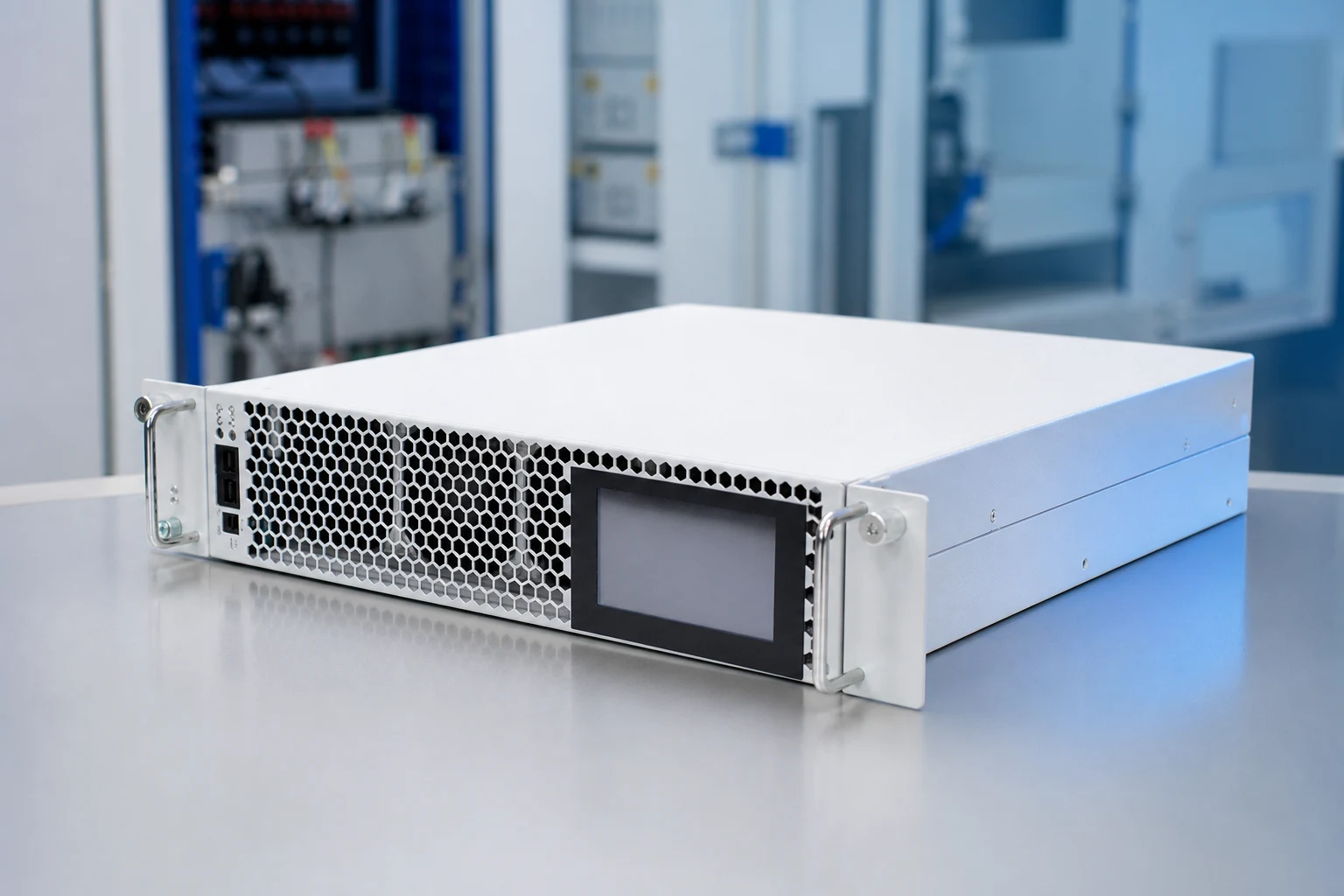
Terminal productivity meetings often collide with power-quality questions. CNBYG can review AHF/APF fit when measured harmonic current is defined. This article does not confirm crane productivity targets, terminal electrification certification, or a guaranteed harmonic result. Browse related guides in the Power Quality System Engineering Guides.

Set the crane-feeder measurement boundary
A logger on an RTG feeder characterizes hoist and gantry duty. A logger at the quay substation or terminal PCC answers a different scope question. Record CT data and how many cranes shared the bus.
For RTG hoist, trolley, and gantry VFD groups on terminal feeders, cover hoist lift, trolley travel, gantry move, idle between moves, and multi-crane coincidence. Note how many RTGs shared the feeder during each window, because coincidence during vessel working peaks can dominate the spectrum.
A practical pre-RFQ record for this application normally includes:
- Single-line of quay substations and RTG feeders.
- Spectra during vessel working peaks, not only idle shifts.
- Notes linked to the crane duty and coincidence state for every export.
- Existing filters and capacitor banks on the quay bus.
- Demand trends across at least one busy vessel window.
| Terminal logging focus | Required attachment | Decision it supports |
|---|---|---|
| Activity at the monitored RTG feeder or quay substation | Current spectrum, RMS trend, load state, CT reference | Local source characterization |
| Activity at the system boundary | Voltage/current trends, transformer and upstream data | Boundary mitigation scope |
| Repeatability across vessel working and shift cycles | Multiple labeled operating windows | Capacity and commissioning planning |
| Connected equipment | Single-line, protection, compensation inventory | Interaction and integration review |
Important: Do not size APF capacity from idle-shift RTG data when the objective covers vessel working peaks (Source: VFD harmonics measurement and APF selection). Multi-crane coincidence can dominate quay feeders.
Separate crane KPIs from distortion claims
Moves-per-hour and harmonic readings answer different questions. A waveform anomaly does not prove a hoist control fault. Keep scopes and acceptance methods separate.
The IEEE 519 overview helps frame PCC talks; terminals still need local operating cases and contractual language.
Operators should also record hoist versus gantry dominance in each window, because those duty cycles stress different parts of the drive line-up. Keep a short note on which berth and which vessel working window produced each file so terminal and electrical teams can reconcile timestamps during RFQ review. Those notes are short, but they keep quay coincidence windows comparable for quotation.
Shortlist after coincidence evidence exists
Consider AHF/APF when harmonic-current reduction at the terminal medium-voltage or PCC boundary is documented with coincidence notes. SVG may fit reactive swings during gantry moves. Passive options need a quay network study.
| Mitigation category | Useful when | Confirm before RFQ |
|---|---|---|
| AHF / APF | Harmonic-current reduction at the terminal medium-voltage or PCC boundary is documented | Spectra, CT plan, thermal path, protection, acceptance test |
| SVG / ASVG | Fast reactive-power support is the primary objective | Voltage profile, existing compensation, controls, commissioning |
| Passive tuning | A system study shows a stable tuned or detuned function | Resonance review, switching policy, maintenance access |
| Operational change | Schedule or staging shifts materially change demand | Owner sign-off and documented implementation |
Assemble a quay RFQ evidence pack
Before suppliers quote, assemble coincidence-labeled RTG spectra, crane-count tables, CT notes, and a marked-up quay single-line. State whether the decision is local crane troubleshooting, terminal-boundary assessment, or harmonic-current mitigation. Present vessel-peak and idle-shift windows separately.
Require the quote to name covered orders, salt-air enclosure limits, and acceptance tests. Include headroom for additional cranes and list filters already on the quay bus. Assign who records coincidence notes and who signs acceptance after berth tests.
Add salt-air enclosure notes, berth outage windows, and a glossary of crane coincidence codes so vessel-peak files are not mixed with idle-shift exports. Include CT polarity checks, sample intervals, and a note describing how many RTGs shared the feeder during each capture. Record expected spare headroom for additional cranes and keep the acceptance checklist owner named before quotation begins.
Review the CNBYG AHF Active Harmonic Filter page against coincidence-labeled quay data. The automotive plant guide on VFD harmonics measurement and APF selection shows how multi-machine coincidence is documented elsewhere.
Integration under terminal constraints
Document salt-air enclosure ratings, cable routes along the quay, and berth outage windows. Acceptance should replay multi-crane windows comparable to the baseline.
The related industrial measurement scenario in APF and SVG selection for automobile manufacturing shows how coincidence notes support post-install checks.
Terminal inquiry package
Provide single-line drawings, coincidence-labeled spectra, crane counts, compensation inventory, and preferred connection points. CNBYG can discuss fit and should not guarantee crane productivity targets, terminal electrification certification, or a guaranteed harmonic result. Submit via the CNBYG contact page.
Frequently asked questions
Where should RTG crane harmonics be measured first?
Begin at the crane feeder or quay substation serving the working group, then expand to the terminal PCC if the objective is plant-boundary mitigation.
Do multi-crane coincidence windows matter?
Yes. Vessel peaks often stack several RTGs on one bus, so coincidence notes are required for capacity discussions.
Can idle-shift data size an APF for a busy berth?
No. Quiet-shift spectra understate hoist and gantry duty that define peak harmonic demand.
Is one measurement enough to select mitigation equipment?
Rarely at busy berths. Crane coincidence, vessel windows, and objective definition decide whether the data is representative.
Can mitigation equipment be sized from connected crane kVA alone?
No. Connected kVA is context; measured harmonic stacks and coincidence logs drive capacity review.
Does this article guarantee a compliance or operational outcome?
No. Terminal operations, network conditions, and commissioning must be verified on site.