Separating Power-Factor and Harmonic-Distortion Decisions
A low displacement power factor and a high harmonic-current level are separate observations. One describes the phase relationship of fundamental current and voltage; the other describes non-sinusoidal current components. A project can have either condition, both conditions, or neither. For industrial distribution systems showing both power-factor variation and nonlinear current, the useful first step is to define the connection point, the operating states that matter, and the decision that will be made from the record. A local feeder result can characterize a source, while a bus or PCC result supports a different system-level discussion. Those results should not be substituted for one another.
Direct answer
A low displacement power factor and a high harmonic-current level are separate observations. One describes the phase relationship of fundamental current and voltage; the other describes non-sinusoidal current components. A project can have either condition, both conditions, or neither. For industrial distribution systems showing both power-factor variation and nonlinear current, the useful first step is to define the connection point, the operating states that matter, and the decision that will be made from the record. A local feeder result can characterize a source, while a bus or PCC result supports a different system-level discussion. Those results should not be substituted for one another.
CNBYG can discuss its product-line context only after the objective is clear. This page does not promise This is an objective-separation article, not a generic APF/SVG comparison, a device-sizing method, or a claim that one technology solves both measured conditions.. For a broader framework, visit CNBYG Power Quality System Guides.
Part 1. Define the decision and electrical boundary
A project team should state whether it is investigating a feeder observation, documenting a shared-bus condition, reviewing reactive-power behavior, planning a capacitor change, or commissioning multiple units. The named objective determines the meter location and the evidence that can be compared. It also prevents a reading from being treated as a conclusion about unrelated equipment.
Record the meter position on the single-line diagram, voltage reference, CT ratio and polarity, aggregation method, and all major equipment active during the interval. Include reactive-power trend, fundamental kW/kvar data, current spectrum, voltage trend, and capacitor-switching state. The site record should name the bus, feeder, transformer secondary, or point of common coupling in plain language so that suppliers and owners interpret the data consistently.
| Decision question | Evidence to retain | Boundary it supports |
|---|---|---|
| What is occurring at a local source? | Current spectrum, RMS trend, load state, CT arrangement | Feeder characterization |
| What is occurring at the common bus? | Voltage/current trend, demand, source and transformer context | Bus or PCC assessment |
| Is an observed condition repeatable? | Time-stamped events across representative operating states | RFQ and commissioning planning |
| What is already connected? | Capacitor, reactor, filter, drive, and protection inventory | Interaction review |
Part 2. Capture representative operating states
The measurement window should reflect the way the system actually runs. For this topic, document industrial distribution systems showing both power-factor variation and nonlinear current during normal operation, transition events, planned switching states, and any coincident nonlinear loads that share the assessed bus. A single quiet period cannot show how a proposed change will interact with the electrical system under a different source or load condition.
Use a time-stamped operations log alongside electrical measurements. Note source configuration, capacitor stage state, major load starts, alarms, and any maintenance bypass. This disciplined record makes it possible to distinguish a repeatable pattern from a short event without asserting that one device caused every visible symptom.
The team can then separate the objective before choosing reactive compensation, harmonic mitigation, or a coordinated study. If the available record does not include representative conditions, state that limitation in the RFQ rather than filling the gap with a nameplate assumption.
Part 3. Keep harmonic, reactive, and operating questions separate
Power-quality discussions often combine harmonic current, reactive-power demand, voltage variation, switching behavior, and protection concerns. They are related through the network but are not interchangeable objectives. A supplier should not be asked to infer a full project remedy from one percentage reading or a connected-load total.
The IEEE 519 standard overview provides authority context for harmonic control, but it does not replace the project decision about the applicable assessment point, data set, network conditions, or contractual criteria. The NEMA standards resource is similarly useful for general equipment context, not for guaranteeing a site result.
| Condition under review | Do not assume | Project question to resolve |
|---|---|---|
| Harmonic-current indication | That it defines reactive-power need | What spectrum and boundary are relevant? |
| Power-factor variation | That it identifies distortion or resonance | What fundamental kvar behavior is present? |
| Capacitor switching event | That a standard reactor setting is suitable | Which scenarios and network inputs were assessed? |
| Multi-unit response | That settings or CT references are correct | What staged evidence supports acceptance? |
Part 4. Product recommendation with a fit boundary
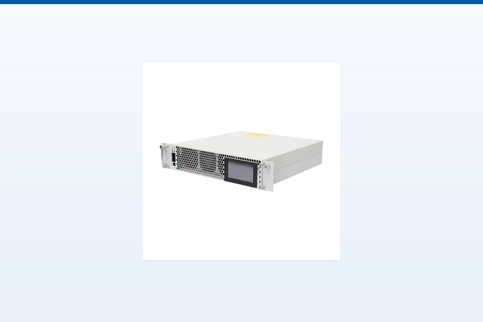
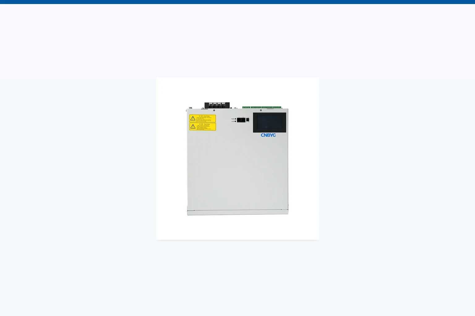
For a defined project objective, review the CNBYG SVG Static Var Generators product page alongside the actual electrical record. The page is a starting point for product-line discussion, not a substitute for capacity selection, protection coordination, or a network study. A correct fit depends on the proposed connection point, system configuration, measurement evidence, controls, thermal environment, and the agreed acceptance method.
Product recommendation: consider SVG Static Var Generators only where its intended role matches a measured and documented objective. Do not recommend it when the main issue is unverified, solely upstream, outside the confirmed scope, or requires a different engineering control. This fit boundary is essential when existing capacitor banks, reactors, or multiple nonlinear sources are present.
Related reading can help the owner frame adjacent questions: the first related CNBYG guide and the second related CNBYG guide. Neither replaces the evidence for the current bus or feeder.
Part 5. Plan integration and staged verification
Integration details belong in the project definition before an order is placed. Document available space, connection arrangement, feeder and bus topology, CT or reference arrangement, cable routing, ventilation, access, communications, alarms, shutdown constraints, and protection responsibilities. Those inputs shape both a practical installation and a transparent commissioning plan.
Staged verification should preserve comparable conditions. Capture the meter location, operating state, unit status, and configuration for each step. Compare results only against the pre-agreed boundary and acceptance method; moving a meter or changing the load mix can change the result without proving an equipment effect.
For industrial-system context, readers may also consult the U.S. Department of Energy Industrial Efficiency and Decarbonization Office. Its resources do not certify a particular installation or establish project compliance.
Part 6. RFQ checklist and fit boundary
An RFQ should include a current single-line diagram, nominal voltage and frequency, source and transformer data, meter files with CT details, operating schedule, load inventory, existing capacitor/reactor/filter details, protection information, proposed installation location, space and cooling information, communications requirements, and the acceptance method. Identify whether the decision is a local troubleshooting task, a common-bus review, reactive-power control, harmonic-current mitigation, or coordinated commissioning.
CNBYG can review the information supplied through its contact page and discuss whether the product line fits the documented scope. It cannot convert this article into a guarantee of This is an objective-separation article, not a generic APF/SVG comparison, a device-sizing method, or a claim that one technology solves both measured conditions.. Where utility coordination, safety, code, critical-load, or unusual operating requirements apply, involve the owner and qualified responsible engineering parties.
Frequently asked questions
Can poor power factor and harmonic distortion occur together?
Yes. They are different electrical observations and can coexist, so measurements should preserve both the fundamental reactive trend and the current spectrum.
Does a capacitor bank solve harmonic distortion?
Not by default. Capacitors address a reactive-power objective only when the system review supports that role; their interaction with harmonic conditions must be evaluated.
When might an SVG be considered?
An SVG may be discussed when dynamic reactive-power behavior is a defined project objective and the connection point, controls, capacity basis, and integration inputs are confirmed.
Can a single snapshot determine the mitigation equipment?
No. The meter location, operating state, time window, system topology, and defined objective determine whether the record is representative.
Does this guide guarantee a compliance or operational result?
No. Applicable requirements, network conditions, acceptance criteria, and commissioning belong to the responsible project process.
What should be included in an RFQ?
Provide a single-line diagram, nominal electrical data, representative measurements, operating schedule, installed equipment, and installation constraints.