For a steady, balanced lagging load using fundamental displacement power factor, Qc = P × [tan(arccos(PF1)) − tan(arccos(PF2))]. Use measured active power and the required before/after power-factor conditions. At an illustrative 800 kW, improving lagging power factor from 0.75 to 0.95 gives about 442.6 kvar of fundamental reactive-power difference. This is a sizing input, not automatic approval of a particular SVG rating, harmonic duty or response speed.
1. Introduction to Static Var Generator SVG Selection
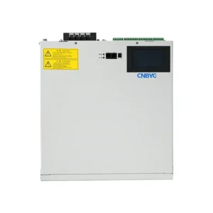
A Static Var Generator SVG is a core device in modern power quality management. The accuracy of SVG capacity selection directly affects the power factor compliance rate of the distribution system, the return on investment cycle, and the long-term service life of the equipment.SVG capacity selection should not blindly pursue a larger capacity. Instead, it should be scientifically calculated according to accurate on-site power quality data, load characteristics, and the expected compensation target.
If the selected SVG capacity is too small, the equipment may operate at full load or overload for a long time and fail to meet utility power factor requirements, such as 0.95 or 0.98. If the selected capacity is too large, it may lead to unnecessary investment and hardware cost waste.
2. Site Survey and Core Parameter Collection Requirements
Before selecting the capacity of a Static Var Generator SVG, key electrical parameters must be obtained through on-site inspection, drawing review, multifunction meter reading, or power quality analyzer testing.
| Parameter | Common Unit | Source / Measurement Method | Technical Purpose |
|---|---|---|---|
| Transformer Capacity ST | kVA | Transformer nameplate or distribution system single-line diagram | Used as the basic reference for evaluating total system load capacity and empirical estimation |
| Actual Active Power P | kW | On-site multifunction meter or power quality analyzer | The key reference data for calculating the actual reactive power gap |
| Original Power Factor cosφ1 | – | Historical electricity bills, real-time meter data, or historical records | Represents the natural power factor before reactive power compensation |
| Target Power Factor cosφ2 | – | Set according to local utility standards or customer requirements | Use the actual utility/project target and the applicable measurement definition |
| Total Harmonic Current Distortion THDi | % | Measured on the main load side using a power quality analyzer | Used to determine whether serious nonlinear loads exist and whether harmonic capacity margin is required |
3. Static Var Generator SVG Capacity Calculation Methods
3.1 Accurate Formula Calculation Method
When the actual active power and power factor data are available on site, the trigonometric formula method should be prioritized to accurately calculate the required reactive power compensation capacity.
Where:
- Qc: Total reactive power compensation capacity required by the system, in kvar.
- P: Maximum actual operating active power of the system, in kW.
- φ1: Original power factor angle before compensation, φ1 = arccos(cosφ1).
- φ2: Target power factor angle after compensation, φ2 = arccos(cosφ2).
3.2 Standard SVG Selection Calculation Example
For a purely illustrative, steady and balanced operating point, assume the actual active power is P = 800 kW. The natural power factor before compensation is cosφ1 = 0.75. Assume the design target power factor is cosφ2 = 0.95.
- Calculate the tangent value of the original angle:
tanφ1 = tan(arccos(0.75)) ≈ 0.882 - Calculate the tangent value of the target angle:
tanφ2 = tan(arccos(0.95)) ≈ 0.329 - Substitute into the formula to calculate the theoretical reactive power gap:
Qc = 800 × [tan(arccos(0.75)) − tan(arccos(0.95))] ≈ 442.6 kvar - Illustrate an optional, assumed 15% allowance. This is not a universal rule and must be justified by the load study and supplier limits. Using unrounded trigonometric values:
442.5864 × 1.15 ≈ 509.0 kvar
The illustrative requirement with that allowance is about 509.0 kvar. A nominal 500 kvar unit would not cover this assumed value before derating. Select from actual available module ratings only after checking operating voltage, current limit, temperature, harmonics, dynamic duty and parallel-control compatibility. No 500/550 kvar product availability is asserted here.
3.3 When Load Measurements Are Not Yet Available
Transformer nameplate kVA alone cannot determine the required SVG kvar. Two loads on the same transformer can have very different active power, displacement factor, harmonic current and dynamic demand. Keep any preliminary allowance explicitly provisional and collect a representative load profile before final selection; do not apply an unsupported fixed percentage of transformer capacity as a purchasing specification.
- Record minimum, normal and peak active/reactive power over relevant operating cycles.
- Separate fundamental reactive compensation from harmonic filtering and unbalance duties.
- Check existing capacitor banks and permitted interaction with the proposed control system.
- Obtain the exact SVG model’s voltage/current, derating, response and supported parallel-operation data.
4. Multi-Module Parallel Operation and Mixed Capacity Selection
In actual engineering projects, large-capacity Static Var Generator SVG systems are usually formed by connecting multiple standard-capacity modules, such as 50 kvar or 100 kvar modules, in parallel.
4.1 Capacity Distribution Logic for Mixed Parallel Operation
When different-capacity SVG modules, such as 100 kvar and 200 kvar modules, need to operate in parallel due to limited space or retrofit requirements, the system controller must support precise multi-module current distribution and control logic.
4.2 Current Determination and Dynamic Distribution
The master control unit must dynamically and proportionally distribute reactive compensation current according to the rated output capacity of each parallel module. This prevents small-capacity modules from being overloaded while large-capacity modules are not fully utilized.
4.3 Parameter Delivery Under Master-Slave Architecture
In a master-slave control architecture, the master unit must collect total current in real time and accurately identify the actual rated capacity of each slave module. The total current calculation and CT ratio delivery must remain strictly consistent to ensure that each compensation command is within the safe operating range of the corresponding module.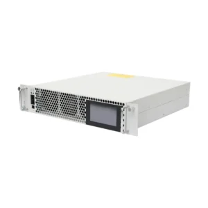
5. Site Commissioning and Sampling CT Configuration Requirements
Proper SVG capacity selection is only the first step. Correct installation and accurate configuration of the sampling CT, or current transformer, are critical to whether the Static Var Generator SVG can output normally and whether the power factor can reach the required target.
5.1 CT Ratio Matching and Setting Requirements
The CT ratio, such as 1000/5 or 2000/5, must be selected according to the total maximum current of the distribution circuit. The CT ratio parameter set in the SVG master control panel must be exactly the same as the physically installed CT.
During commissioning of a multi-module parallel SVG system, the CT ratio set by the master unit must be accurately delivered to each parallel sub-module. If the internal logic deviates during total current calculation or CT ratio delivery, the SVG may incorrectly identify the reactive power condition of the grid, resulting in no output, overcompensation, or parallel resonance with capacitor banks.
5.2 CT Polarity and Physical Installation Position Error Prevention
During on-site wiring, the polarity and installation position of the sampling CT are common sources of commissioning failure.
- Installation position: The CT must be installed on the grid side or the load side, and the corresponding sampling position mode must be selected correctly in the SVG control system.
- Incorrect position setting: If the CT is physically installed on the load side but the software is set to grid-side sampling, the SVG may output in the opposite direction, causing closed-loop control failure.
- Strict polarity correspondence: Confirm CT direction, phase assignment and S1/S2 connections from the exact SVG wiring diagram and the selected grid-side or load-side sensing arrangement. Do not infer a universal connection from a generic page, reverse a live CT circuit, or open an energized CT secondary.
5.3 External Grid Environment and Abnormal Fault Prevention
In industrial or mining sites with harsh wiring conditions, SVG equipment often faces serious challenges from the external power grid.
5.4 External Surge and Grid Voltage Fluctuation Impact
Some sites have severe voltage fluctuations, lightning strikes, switching surges, or circuit breaker operation surges. These external surges may enter the equipment through power lines and damage internal low-voltage control components, such as switching control relays and driver boards.
5.5 On-Site Engineering Judgment Criteria
When component failures such as relay damage occur, engineering technicians should investigate historical surge records, voltage mutation traces on the transformer side, and whether the customer’s external wiring has short circuits, cross-voltage problems, or other abnormalities. This helps determine whether the damage was caused by harsh external conditions or equipment quality issues.
6. Conclusion and Engineering Optimization Recommendations
Scientific SVG selection: When conditions allow, the selection principle should be based on measured data, formula calculation, and engineering safety margin. Any allowance must be justified for the actual load profile, operating conditions and model limits; 1.15 is only the illustrative assumption used above.Strict wiring inspection: Before on-site commissioning, technicians should use multiple meters or a phase angle meter to verify CT ratio, polarity, and phase sequence to ensure the accuracy of basic electrical data.Enhanced protection: For sites with heavy reactive power impact, frequent lightning, or high surge risk, high-grade surge protective devices, SPDs, and isolation devices should be installed at the SVG input side and control circuit to improve the overall impact resistance of the system.
A properly selected and commissioned Static Var Generator SVG can effectively improve power factor, reduce reactive power penalties, enhance power quality, and ensure stable operation of industrial distribution systems.