


Campus central-plant VFD harmonic work starts with a documented electrical boundary and operating mode. A central plant can move between cooling, heating, shoulder-season, and staged conditions while chillers, pumps, cooling towers, and air handlers change their contribution. The record needs to say what was running when it was captured.
Use the power quality system guides for broader planning context. This article explains how to frame a campus central-plant review; it does not certify a facility result.

Part 1. Define the central-plant electrical question
Start with the decision the data must support. A measurement at one chiller drive can describe that local connection, while a central-plant feeder can capture multiple drive groups. An agreed PCC is a separate system boundary, so the observations are not interchangeable.
Mark the meter position, voltage reference, CT ratio and orientation on the one-line diagram. Retain the aggregation interval, capture duration, active load group, and supply arrangement. A reviewer can then understand the electrical scope without treating an unlabeled screen capture as a plant-wide finding.
Important: Do not use a drive-terminal reading as proof of a feeder or PCC result. The electrical boundary, plant operating state, and project acceptance method must be defined together (IEEE 519 overview).
Part 2. Compare plant modes instead of isolated snapshots
Central plants rarely operate in one fixed configuration. Cooling mode can use a different combination of chillers, chilled-water pumps, condenser-water pumps, and cooling-tower fans than a reduced-load or changeover period. Build named operating states before deciding which records should be compared.
| Plant-mode question | Record with the electrical data | Why it matters |
|---|---|---|
| Which chiller trains were enabled? | Equipment identifier and staging state | The feeder load can change with staging. |
| Which pumps and towers were running? | Drive group, speed state, and time stamp | Auxiliary drives can change the coincident load. |
| Was the plant in cooling, heating, or transition? | Mode and schedule note | Different modes answer different planning questions. |
| Did a source or equipment state change? | Start, stop, bypass, or transfer note | A transient is not automatically a steady basis. |
The existing commercial HVAC VFD harmonic measurement guide is a useful sibling reference. A campus plant record still needs its own equipment and operating-mode log.
Part 3. Build a record that separates harmonic and reactive-power objectives
Harmonic-current mitigation and reactive-power behavior are different project questions. Before reviewing a device, state which electrical objective is being investigated and at which boundary. A measurement plan that mixes the two objectives can obscure the decision rather than clarify it.
| Review item | Keep constant or disclose | Decision use |
|---|---|---|
| Electrical objective | Harmonic current, reactive power, or another documented concern | Keeps the review scope explicit. |
| Electrical location | Drive input, feeder, or agreed PCC | Prevents unlike records being compared. |
| Time basis | Interval, duration, and clock reference | Connects the record to the plant-mode log. |
| Acceptance context | Project metric and responsible reviewer | Avoids turning a guide into a compliance verdict. |
The DOE Industrial Technologies Office resource describes broad industrial context only. It does not define an acceptance limit or equipment scope for a particular campus installation.
Part 4. Keep the feeder, PCC, and drive readings distinct
Meter location changes the question being answered. A drive terminal can characterize one unit, while a feeder can show interaction among several loads. An agreed PCC can support a broader supply-side assessment, so write the location into every record title and report table.
| Record location | What it can help describe | What it cannot prove alone |
|---|---|---|
| Individual drive input | Local drive behavior | Shared-feeder or PCC behavior. |
| Central-plant feeder | Coincident central-plant load behavior | A different upstream boundary. |
| Agreed PCC | Defined supply-side condition | The root cause of every plant symptom. |
| Temporary test point | A named diagnostic interval | A permanent operating conclusion. |
For a measurement checklist that applies before a product discussion, see power quality metering before an APF or SVG RFQ. The measurement plan should remain tied to the actual campus diagram.
Part 5. Review SVG or AHF paths against a defined scope
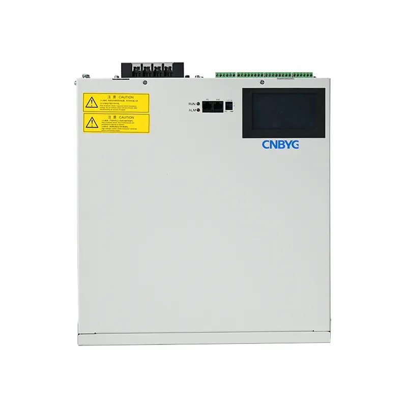
An SVG Static Var Generator review can be considered when dynamic reactive-power behavior is the defined objective. It requires a stated connection point, load behavior, CT arrangement, protection review, installation space, cooling, cable routing, and acceptance method. An AHF Active Harmonic Filter discussion follows a different path when measured harmonic current is the agreed objective.

The fit boundary is practical: do not choose either path from connected chiller motor kW alone or from a single local screenshot. An upstream event, a protection issue, or an undefined objective needs more definition before product selection.
Part 6. Prepare a campus central-plant inquiry
Provide a project package that identifies both the electrical location and the plant mode. This lets a product discussion start from a reviewable scope instead of an assumed capacity.
| Buyer should provide | Why it matters |
|---|---|
| One-line diagram and nominal system information | Establishes the electrical boundary and supply context. |
| Meter, CT, and voltage-reference locations | Lets the reviewer locate each recorded condition. |
| Representative voltage and current records | Shows the evidence behind the request. |
| Cooling, heating, and transition-mode log | Connects the record to plant operation. |
| Chiller, pump, fan, and other load inventory | Identifies the load groups that can be coincident. |
| Existing filters, capacitors, and protection information | Identifies integration constraints. |
| Equipment-room, cooling, cable, and communications limits | Tests installation feasibility. |
CNBYG can discuss product-line fit for a defined objective. Use the central-plant project information form to begin that discussion; a general guide cannot guarantee a campus electrical or operational result.
Frequently asked questions
Where should a central-plant power-quality meter be placed?
Place it at the electrical location that matches the decision being made, then record that position on the one-line diagram. A drive input, central-plant feeder, and PCC are different boundaries.
Which campus central-plant modes should be logged?
Log cooling, heating, transition, reduced-load, staging, start, stop, bypass, and relevant supply states. Each record needs the equipment combination that was active during its interval.
Is a chiller drive reading the same as a feeder or PCC record?
No. A drive reading describes one local point, while a feeder or PCC record can include a different combination of loads and supply conditions.
Are harmonic-current and reactive-power objectives the same?
No. They are separate electrical objectives that should be named before the measurement plan and equipment review are defined.
Can connected chiller motor kW select SVG or AHF equipment?
No. Connected motor kW does not replace a defined objective, electrical boundary, CT arrangement, representative operating record, installation scope, or acceptance method.
What should be included with a campus central-plant inquiry?
Send the one-line diagram, nominal system information, meter and CT positions, representative records, plant-mode log, load inventory, existing equipment, and installation constraints so the inquiry can be reviewed in context.