Harmonics in Variable Refrigerant Flow HVAC Systems
VRF HVAC harmonics arise when electronic power conversion in variable refrigerant flow equipment draws nonsinusoidal current from the supply. Their significance depends on the installed equipment, operating load, network impedance and other loads sharing the distribution system. Investigate the actual current spectrum and voltage behavior before selecting mitigation. Do not assume that every VRF installation needs an active harmonic filter, or that equipment capacity alone determines the harmonic current. A useful assessment separates waveform distortion from voltage events, wiring faults, refrigerant faults and ordinary HVAC control problems.
This guide focuses on the electrical investigation of VRF equipment. It complements the broader commercial HVAC feeder and PCC investigation by addressing distributed outdoor units, changing compressor demand and the evidence needed from the actual VRF installation. Electrical measurements and equipment work belong to qualified personnel following approved procedures.
Understand the electrical load without guessing its topology
VRF systems use electronic controls to vary compressor operation. The input stage, filtering arrangement and control design influence the current drawn from the building supply. Obtain model-specific documentation rather than inferring internal circuitry from the words “inverter” or “variable speed.”
Two systems with similar cooling capacity can have different input behavior. Their operating states may also differ substantially during heating, cooling, partial occupancy or defrost where applicable. The installed combination of units, supply arrangement and simultaneous demand matters more than a generic description of the equipment family.
Keep electrical and HVAC diagnoses connected but distinct. A compressor alarm may result from a supply event, yet many alarms concern equipment or refrigeration conditions. Request the actual alarm code and manufacturer interpretation. A harmonic measurement does not replace the service provider’s mechanical and controls investigation.
Define the reason for the harmonic assessment
The measurement plan should answer a specific question. Examples include whether a VRF feeder contributes materially to supply distortion, whether a proposed expansion changes the building’s harmonic profile, or whether a contractual requirement is met at an agreed boundary. Each question needs a clearly identified location and operating condition.
A warm distribution component or repeated protection operation also requires investigation of loading, connections and protection behavior. Do not label it a harmonic problem until evidence supports that mechanism. If a confirmed defect needs repair, address it through the electrical maintenance process before relying on compensation equipment.
Record the initial symptom, affected circuits, timestamps and recent changes. A new outdoor unit, changed operating schedule or building fit-out can alter demand. Those records help distinguish a longstanding condition from a problem introduced by a modification.
Measure the VRF feeder and its upstream supply
Start from an accurate single-line diagram. Identify the VRF feeders, common upstream board and the building supply point relevant to the assessment. Record other substantial nonlinear loads that operate on the same distribution path. Measuring only one outdoor unit cannot establish the combined behavior at the building supply.
Use synchronized recordings when comparing locations. A current spectrum on Monday and a supply voltage trend on Friday may describe different conditions. Simultaneous or carefully coordinated records allow the engineer to compare changes in VRF demand with upstream electrical behavior.
The meter placement guide explains how measurement boundaries affect interpretation. Choose instruments with documented capabilities for the quantities, events and methods required. Temporary connections, sensor selection and instrument ratings must be suitable for the actual installation.
| Assessment question | Measurement evidence | Operational record | Interpretation limit |
|---|---|---|---|
| Does the VRF feeder contribute harmonics? | Current spectrum at feeder and upstream point | Units enabled and representative compressor demand | Other loads may contribute at the shared point |
| Does supply voltage become distorted? | Voltage spectrum and relevant network condition | Concurrent VRF and other major load operation | Current distortion alone cannot answer this |
| Are trips associated with voltage events? | Timestamped voltage events and equipment alarms | Actual alarm codes and unit operating state | Harmonics may be unrelated to the trip |
| What current must mitigation handle? | Harmonic current by component across operating modes | High and low demand conditions | Installed cooling capacity is not a filter rating |
| Did an expansion change performance? | Comparable before-and-after recordings | Added equipment and changed schedules | Weather and occupancy can affect comparison |
These are qualitative investigation steps. Apply the agreed standards, utility requirements and equipment limits rather than treating the table as an acceptance specification.
Capture representative compressor operation
VRF demand changes with occupancy, weather, setpoints and simultaneous heating or cooling needs according to the actual system design. Record conditions associated with the complaint or intended design case. Include lighter operation as well as substantial demand where those states are relevant.
A percentage distortion figure can increase during light load even when absolute harmonic current is smaller. Keep the fundamental and RMS current quantities alongside the distortion result. For equipment selection, the absolute current and component profile are essential information.
Seasonal limitations should be explicit. A survey conducted during mild weather may not represent peak cooling or a winter operating condition. Do not invent a worst-case multiplier to compensate for missing measurements. Arrange additional recording or use manufacturer-supported application information with its assumptions clearly stated.
Read the harmonic spectrum explanation before reducing the entire investigation to one THD number. Individual components and their variation with load can be more useful for diagnosing the actual interaction.
Distinguish feeder current from building voltage quality
Nonlinear current flowing through the network can contribute to voltage distortion. The effect depends on the network impedance and other connected loads. A VRF feeder current measurement therefore needs context from the upstream system rather than a universal conclusion based on one percentage.
At the building supply, multiple load groups contribute. Lighting, lifts, computers and other drives may overlap with VRF operation. Use feeder comparisons and operating logs to investigate contributions. Avoid claiming that the largest cooling load must be the dominant harmonic source without measurements.
For a utility or contractual assessment, identify the actual point of common coupling and the adopted requirements. A local branch feeder and a utility-defined boundary serve different purposes. An internal engineering target can be useful, but it should be labeled separately from a contractual compliance statement.
Verify the measurement method and sources
The IEC 61000-4-7 publication is a relevant reference for harmonic measurement methods. Grouping, aggregation and instrument settings affect how results are compared. Record the adopted method and instrument evidence in the assessment report.
The IEC 61000-4-30 publication addresses power quality measurement methods more broadly. Confirm the applicable edition and the methods required for the project’s purpose. A meter name or advertising statement is not independent proof that every method is implemented.
This guide does not assign a universal harmonic limit to VRF equipment. Local rules, utility arrangements, assessment boundaries and equipment standards need to be checked for the actual project. Keep the scope of each source clear when preparing specifications or discussing compliance with a customer.
Evaluate mitigation only after identifying the mechanism
First confirm installation condition and manufacturer requirements. Incorrect sensing, poor connections or equipment faults should not be hidden behind a filtering proposal. Review the VRF documentation and coordinate any supply-side changes with the HVAC equipment provider.
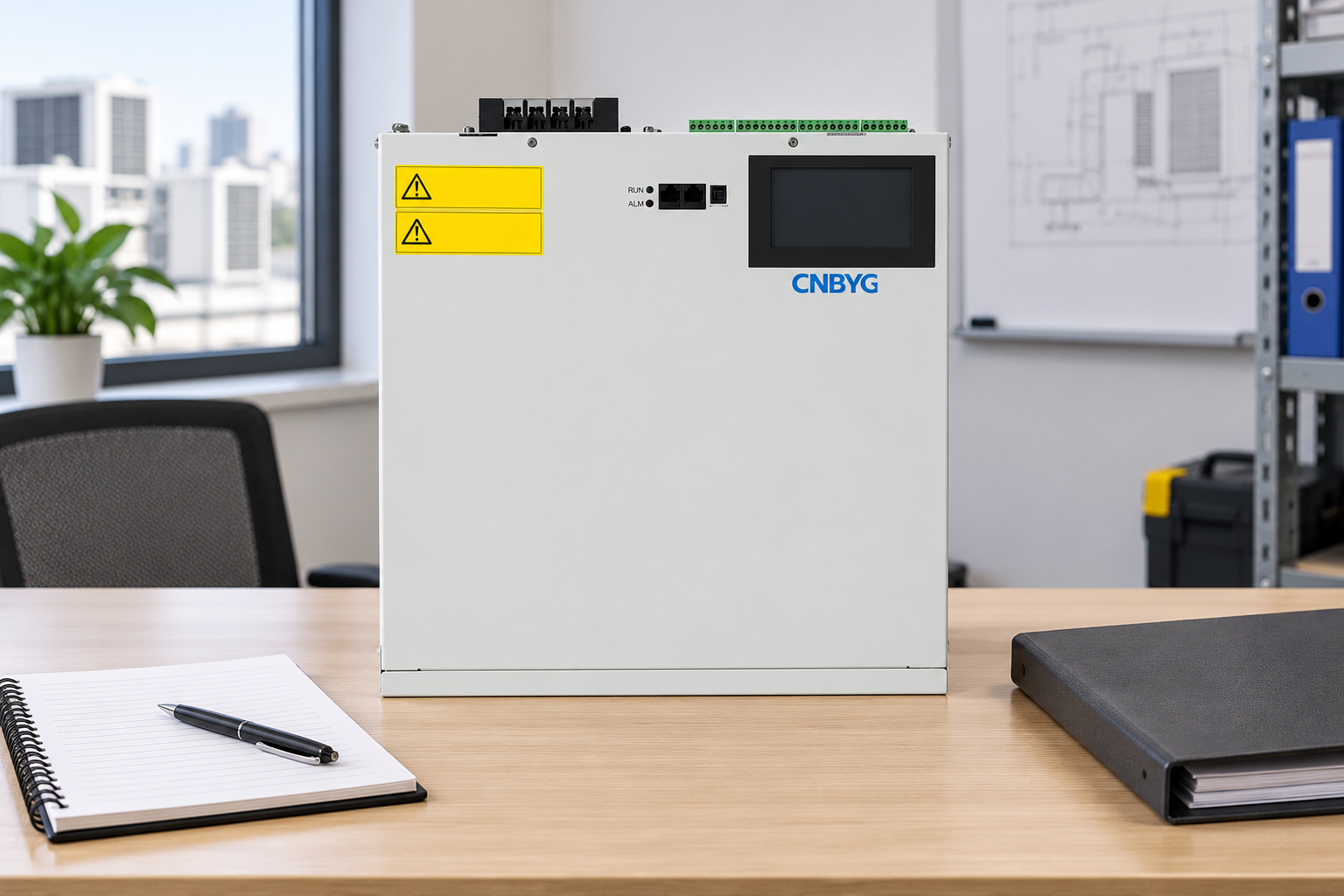
Where compatible harmonic current mitigation is justified, evaluate the CNBYG active harmonic filter against the actual load and network. Required information includes harmonic current components, operating range, supply arrangement, sensing location and installation conditions. Manufacturer confirmation is necessary for the proposed application.
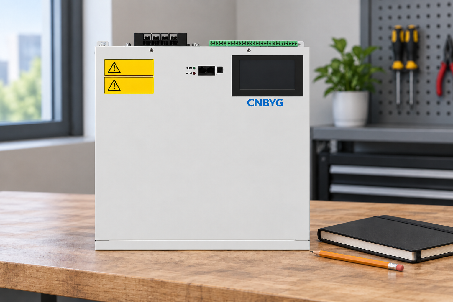
The product exterior illustration supports the equipment review. It shows no installed wiring and makes no claim of measured improvement. Safety sticker text is simplified for illustration; actual equipment labels and approved instructions govern installation and operation.
Do not select a filter only from cooling capacity, transformer capacity or an isolated THD percentage. Also distinguish harmonic mitigation from reactive compensation. A poor power factor assessment needs the relevant power quantities and network information. Capacitors should not be added blindly to a distorted network because unsuitable resonance or component stress can become relevant.
Supply interruptions, voltage dips and equipment ride-through require their own evaluation. A filter is not a backup supply. State the intended remedy narrowly enough that the supplier and building owner can agree on what the equipment is expected to improve.
Commission against representative operation
Prepare an acceptance plan before procurement. Identify measurement points, adopted methods, operating modes and the original symptoms to be reviewed. If the goal concerns building supply performance, testing only at the filter terminals is insufficient.
Repeat measurements after installation with the VRF system in relevant operating states. Record changes in weather, occupancy and other loads. A lighter load period can produce different readings even without a mitigation device, so the report needs enough context to support the comparison.
Retain the baseline, final settings, sensing arrangement, alarms and maintenance requirements. If equipment is added later, review the available capacity and repeat proportionate checks. Avoid assuming that the first acceptance test covers all future expansions or seasonal operating conditions.
Further learning: standards and monitoring
The following NPTEL lecture explains general power quality standards and monitoring concepts. It supports understanding of the measurement plan and reporting boundaries. It is not VRF manufacturer training or a certification of the illustrated filter.
Watch Power Quality: Standards and Monitoring
Frequently asked questions
Do all VRF systems produce the same harmonics?
No. Input design, installed configuration and operating conditions affect current behavior. Use model-specific information and measurements rather than applying one generic spectrum to every VRF installation.
Can cooling capacity be used to size an active harmonic filter?
Cooling capacity alone does not establish harmonic current. Selection requires measured electrical current components across representative operation, the supply arrangement, sensing requirements and manufacturer application confirmation.
Are VRF drive trips always caused by harmonics?
No. Review actual alarm codes, voltage events and equipment operating conditions with the service provider. Supply disturbances, equipment faults and controls or refrigeration issues need to be distinguished.
What should be retained after commissioning?
Keep measurement locations, adopted methods, representative operating conditions, before-and-after evidence, settings, sensing arrangements and maintenance information. State any seasonal or load conditions that were not covered.