


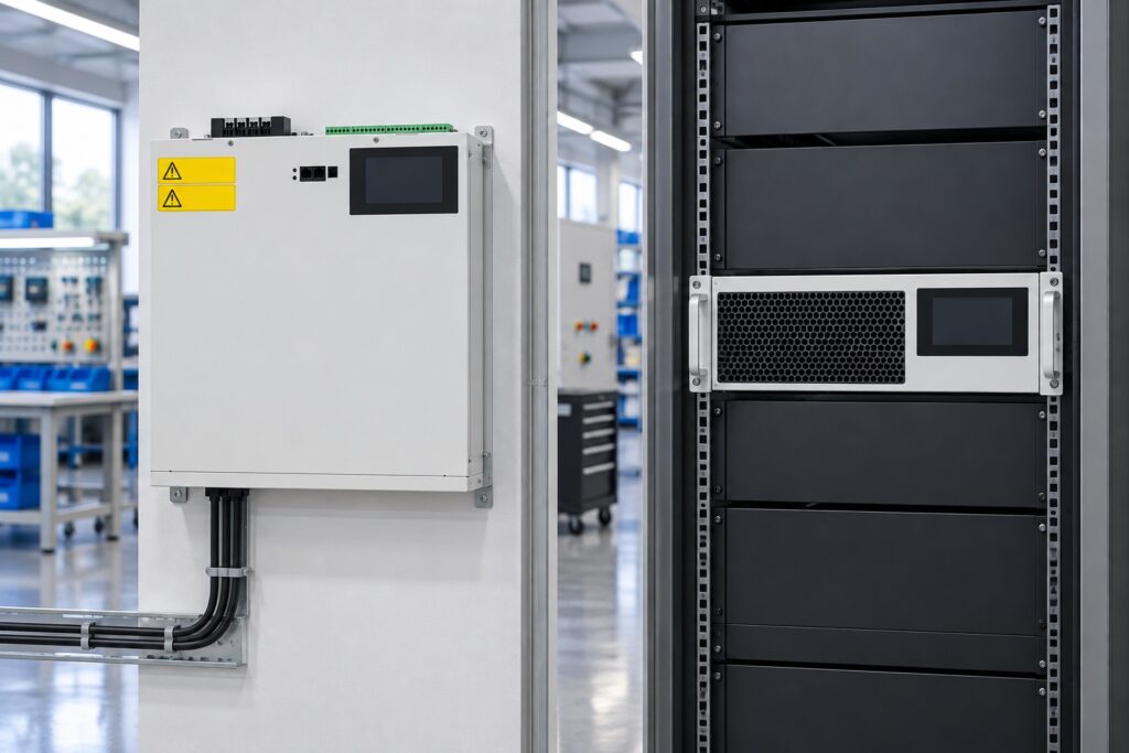
Wall-Mounted vs Rack-Mounted SVG Selection
Wall-mounted vs rack-mounted SVG selection is mainly an integration decision. A wall unit provides a self-contained enclosure at a suitable wall or frame location. A rack module fits into a designed cabinet that supplies mechanical support, protection, airflow, bus or cable interfaces and service access. Choose only after confirming reactive-current duty, voltage and wire system, because enclosure style cannot correct an undersized or incompatible SVG. Then compare available space, heat removal, ingress protection, cable routing, maintainability, expansion and assembly responsibility.
The electrical duty comes first
Both formats can serve reactive-power compensation, but they are not automatically interchangeable. Confirm the offered model’s nominal voltage, frequency, phase/wire arrangement, current or kvar capability, thermal limits and supported control functions. Use time-based load measurements to determine the required inductive and capacitive range. Record minimum load as well as peak production because leading power factor can appear when fixed capacitance remains connected at light load.
The CNBYG SVG product family is the product context used for the reference images. Obtain the current model datasheet and dimension drawing before allocating space. A photograph cannot establish dimensions, clearances or ratings.
Format comparison table
| Selection factor | Wall-mounted SVG | Rack-mounted SVG | Required check |
|---|---|---|---|
| Mechanical location | Needs a verified wall or support frame and clear service area | Needs a compatible rack/cabinet and rail support | Dimension drawing, mass, mounting details and site structure |
| Environmental protection | Provided by the unit enclosure only to its stated rating | Depends on module plus complete cabinet design | Dust, moisture, room class and required ingress protection |
| Cooling | Room and unit clearances must support specified airflow | Cabinet airflow must serve every module without recirculation | Model heat data, airflow path, ambient and peak duty |
| Power/CT wiring | Cables route to the wall enclosure and must retain bend space | Cabinet can integrate bus, protection, CT terminals and communications | One-line, conductor sizes, bend radius and segregation |
| Expansion | Additional wall area and coordinated parallel operation are needed | Spare rack positions may support modular growth if engineered | Future duty, sharing method, protection and thermal capacity |
| Service | Direct access without opening a shared cabinet may be useful | Module replacement may be organized within a common cabinet | Isolation, lifting, front/rear access and spare strategy |
The correct format is the one whose complete installation satisfies these checks. A convenient-looking mounting position is not evidence of electrical or thermal suitability.
When a wall-mounted SVG fits well
A wall unit can work where floor space is scarce and a structurally suitable surface is close to the compensation point. It can separate the SVG from a crowded switchboard and offer straightforward exterior access. The design must still provide permitted working space, cable entry, protection, isolation and room for removal. Do not mount it above equipment that blocks service or exposes technicians to unrelated energized parts.
Verify the wall, frame, anchors and seismic requirements where applicable. Use the manufacturer’s mounting pattern and mass. Maintain required distance from ceilings, adjacent enclosures and heat sources. A narrow corridor may physically accept the unit but fail access or egress rules.
Cable routing can decide the location. Long or congested runs add cost and voltage drop and may complicate CT wiring. Keep current-transformer circuits within the approved design and document polarity and phase assignment. The power-quality baseline guide helps establish measurement points before the enclosure location is finalized.
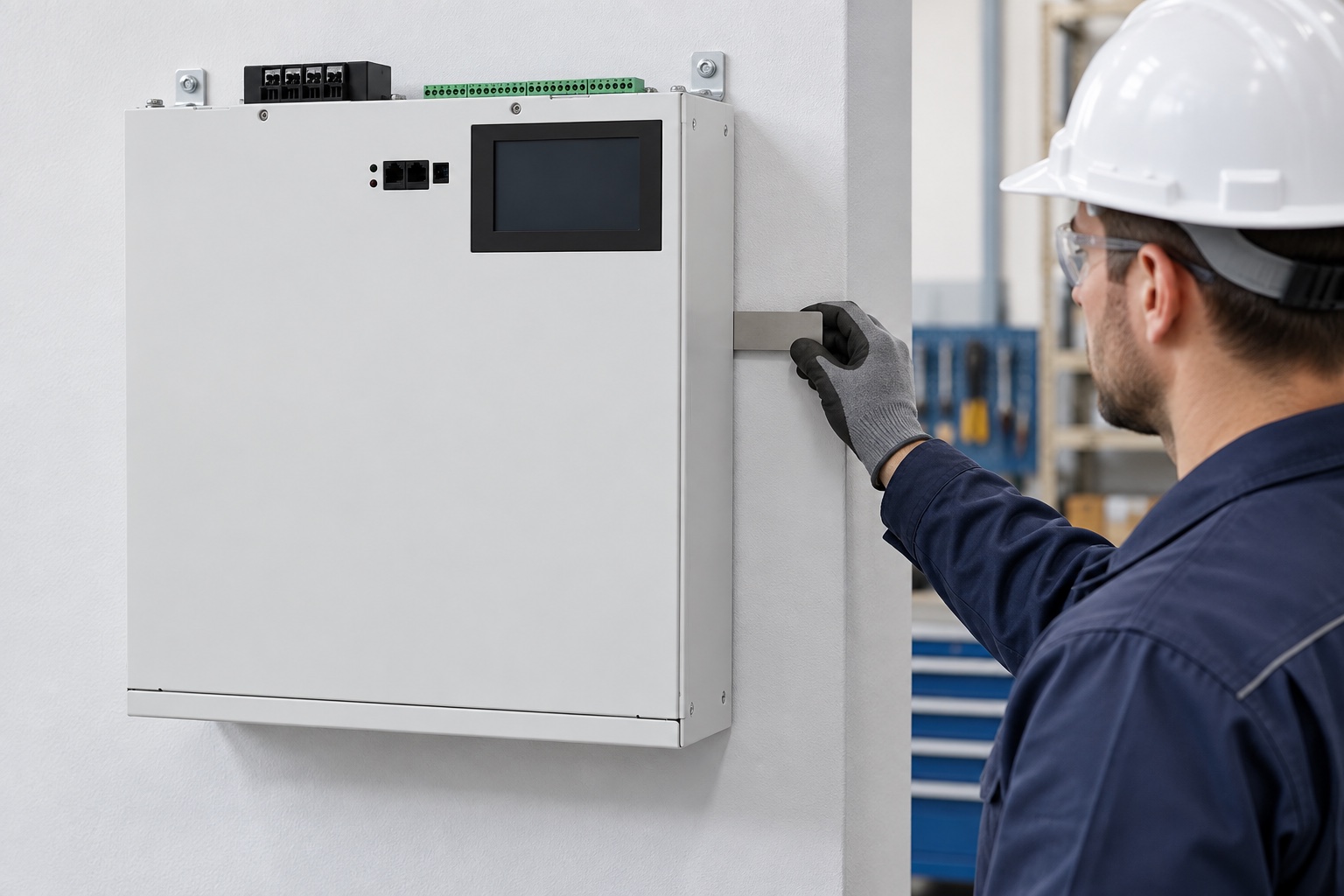

Image: illustrative access review. The actual clearance and support requirements come from the selected model’s instructions.
When a rack-mounted SVG fits well
A rack module can suit a new or purpose-built compensation cabinet, especially where the project needs multiple coordinated modules, common protection, bus integration or organized communications. The cabinet designer controls rails, support, cable segregation, door access and airflow. This integration is an advantage only when responsibility is explicit.
Do not assume that any standard-looking rack accepts the module. Confirm mounting width, height units, depth, mass distribution, support rails, connector access and removal path. A front-mounted flange alone may not carry the full load. Check whether service requires front, rear or side access.
Parallel modules need more than empty slots. The cabinet requires adequate bus and protective capacity, thermal headroom, CT/control coordination and a defined load-sharing method. See the parallel SVG module guide when expansion is part of the business case.

Image: unenergized cabinet mock-up used to review mechanical fit; it is not an approved final assembly.
Cooling often decides the format
Power-electronic losses become heat inside the room or cabinet. Ask for model-specific heat rejection at the relevant load and voltage. For a wall unit, verify ambient air temperature and unobstructed inlet/outlet clearances. For a rack design, map cool-air entry and hot-air exit for every module. Prevent discharged air from returning to the intake of another module.
A cabinet fan rating alone does not prove component temperature. Account for filters, pressure drop, neighboring heat sources, altitude where relevant, loss of a fan and dirty-filter condition. Place temperature sensors where they reveal the limiting condition, then validate the finished assembly at representative peak duty.
The AHF cabinet cooling article discusses a related power-electronic airflow workflow. Use the SVG manufacturer’s own heat and clearance data for this project. NPTEL IIT Bombay’s electronics-cooling lecture below supplies neutral background; it does not specify this product.
Enclosure protection and assembly responsibility
IEC 60529 defines IP degrees of protection provided by enclosures. Select an appropriate requirement from the actual dust, moisture and access conditions. A higher IP code can restrict natural airflow and may require a different cooling solution; do not upgrade the number without checking thermal consequences.
For a rack module, the completed cabinet is the relevant protected assembly. Identify who is responsible for the cabinet design, component compatibility and verification. IEC 61439-1 provides general rules for low-voltage switchgear and controlgear assemblies. Apply the edition and local requirements specified by the project.
A wall enclosure also needs correct cable glands, unused-entry sealing and maintained door/cover integrity. Drilling an unapproved opening or blocking an air path can defeat both environmental and thermal assumptions.
Commissioning checks for either format
Before energization, verify model and rating, mechanical fastening, protective conductor, power connections, CT ratio/polarity/phase, protection settings, communication wiring, airflow clearance and removal of shipping materials. Confirm isolation and stored-energy procedures from the manual. Do not use an article as an energized-work instruction.
At startup, record firmware and settings, alarms, ambient condition, load state, source current, SVG output and power factor at the defined measurement point. Test representative inductive and capacitive states if safely available. The SVG installation and commissioning guide provides additional integration context; the selected model manual controls the final procedure.
Procurement checklist
Issue the one-line diagram, load trend, voltage/wire system, proposed location, photographs, room environmental data and cabinet drawings. Request the exact dimension drawing, mass, mounting kit, cable-entry details, heat loss, airflow direction, clearances, IP rating, CT requirements, protection, communications and service-access needs.
For a rack design, request cabinet responsibilities, rail support, bus connection, module-removal method and future-slot assumptions. For a wall design, request anchor pattern, allowable orientation and cable-bend requirements. In both cases, state commissioning and acceptance deliverables. Compare complete installed scope rather than module prices.
Plan maintenance access before fixing the layout
Draw the removal path, not only the operating position. The team may need to remove filters, fans, covers or a complete module using approved procedures. Check door swing, lifting aids, nearby cable trays and whether another energized section would block safe access. A rack module that can slide out still needs support for its mass and enough cable or connector strategy to avoid damage. A wall unit needs a safe working platform when mounted above floor level.
Identify the isolation boundary and how personnel will verify it. If the SVG shares a cabinet with other equipment, determine whether service can occur without exposing adjacent live parts. Labels, barriers and interlocks belong to the completed design. Use the site electrical-safety program and manufacturer instructions; this article does not authorize live work.
Maintenance planning also affects spare strategy. Record the exact model, firmware, settings file, CT arrangement and module position. For parallel racks, a spare must be compatible with the controller and sharing scheme. For distributed wall units, keep a location-based asset list. Good access and records reduce restoration time without changing the electrical rating.
Neutral video: electronics cooling
This NPTEL IIT Bombay lecture introduces electronics-cooling principles relevant to airflow planning. It is general education, not a CNBYG installation instruction.

Frequently asked questions
Is a rack-mounted SVG more powerful than a wall-mounted SVG?
Not necessarily. Format does not prove electrical rating. Compare the exact models’ current/kvar capability, voltage, thermal limits and supported functions.
Can I install a rack SVG in an existing cabinet?
Only after verifying rails, support, bus/protection, airflow, access, CT/control wiring and completed-assembly requirements. Empty rack space alone is insufficient.
Does a wall SVG need its own room ventilation calculation?
Its losses enter the room. Use model-specific heat data, room ambient limits and concurrent equipment loads to verify ventilation or cooling.
Which format is easier to expand?
Rack systems may organize modular growth, while wall systems can add distributed units where space exists. Either approach requires coordinated controls, protection, CTs and thermal capacity.
Selection rule
Choose a wall SVG when a verified structure, local cable route and independent service access make it the cleaner installation. Choose a rack SVG when a designed cabinet provides better integration, modularity and environmental control. Do not finalize either until electrical duty, thermal behavior, protection and maintainability pass a documented review.