Harmonics in Water Pumping Stations
Pumping station harmonics usually come from nonlinear electrical equipment such as variable-frequency-drive input converters, rather than from water flow itself. Assess them across duty-pump combinations, speed changes, standby operation and the permitted backup-supply configurations. Measure harmonic amperes and voltage distortion at the relevant feeders and supply interface before selecting mitigation. A high current-distortion percentage on one lightly loaded pump does not establish the station’s overall compliance or the correction current required. Keep electrical distortion separate from cavitation, mechanical vibration and pressure-control problems, which need their own evidence and remedies.
Map the pumping station’s electrical and operating arrangement
Begin with a verified single-line diagram. Identify the incoming supply, transformer, switchboards, pump feeders, drive input arrangements, control supplies and any existing power-factor correction equipment. Note which pumps can operate together and whether the station uses a generator, alternate incoming supply or automatic transfer arrangement.
Do not infer the converter design from the presence of a variable-frequency drive. Input reactors, passive filters and active front ends may be optional or model-specific. Record what is actually installed, including bypass equipment. A drive in bypass and a drive under electronic speed control can present different electrical conditions even though they operate the same pump.
Add an operating map: duty and standby roles, required flow and pressure, pump speed range, reservoir conditions and approved sequencing. The aim is to connect measurements to repeatable operating conditions. A generic load label such as normal operation is insufficient when a station alternates between one pump overnight and several during peak demand.
Choose representative duty states
Capture individual duty pumps, permitted combinations, typical low-speed operation and representative higher demand. If multiple pumps rotate duty, identify the actual machines and drives operating during every sample. Similar nameplate power does not guarantee identical input-current behaviour, especially when different drive generations or options have been installed over time.
Observe standby and transition periods separately. A lightly loaded control supply or idling drive may have a large percentage distortion but low current. A pump starting or a drive changing operating mode can create a brief event that should not be confused with a sustained harmonic condition. Record timestamps and the controller’s approved operating-state information.
For wastewater and drainage stations, connect the electrical records to available process conditions without inventing a uniform duty cycle. For irrigation or water distribution, include the relevant seasonal or demand conditions if they occur within the survey period. If the survey misses a critical state, list it as missing evidence and plan a later check.
| Station state | Electrical record | Process record | Why the distinction matters |
|---|---|---|---|
| One duty pump running | Feeder current spectrum and supply voltage | Pump identity, speed and flow condition | Establishes the individual drive contribution |
| Two or more pumps running | Shared bus voltage and individual feeder currents | Actual combination and control demand | Reveals combined loading without assuming harmonic addition |
| Reduced-speed duty | Fundamental current and harmonic amperes | Speed command and relevant pressure or level | Prevents percentage distortion from being read without its denominator |
| Duty changeover | Timestamped waveform or event records | Approved sequence and transfer time | Separates transitions from steady operation |
| Drive bypass, where authorised | Supply current and voltage | Confirmed bypass mode and process condition | Avoids comparing two different electrical arrangements as if identical |
| Generator operation | Voltage distortion, current spectrum and source configuration | Permitted pump combination and transfer state | Checks performance on the actual backup source |
The table is an investigation plan, not a numerical acceptance standard. Use project-specific criteria and qualified personnel for any electrical connection or operational test. Measurement instrumentation and spectral definitions should follow the agreed method; IEC 61000-4-7 provides relevant harmonic and interharmonic measurement guidance.
Measure feeders and the shared supply
Measure a pump feeder to locate its contribution, and measure the shared supply to understand station-wide behaviour. Agree the point of common coupling with the responsible engineer or utility before applying supply-interface criteria. The incoming switchboard and an individual drive terminal are not automatically interchangeable compliance locations.
Use suitable current sensors and voltage connections with the instrument configured for the actual network. Verify current-transformer ratio, polarity and phase association. Installation and removal require the site’s electrical-safety procedures. A pump station can remain hazardous even if a particular pump is stopped; do not equate operational standby with safe electrical isolation.
For simultaneous measurements, align timestamps and use comparable instrument methods. Where only one analyser is available, document the limitations of separate measurements and choose operating states that can be reproduced safely. The power-quality meter placement guide helps define upstream and feeder positions.
Retain voltage distortion, current spectrum, fundamental current, harmonic amperes and active and reactive power. Include the instrument location in every export. A report without its measurement point cannot reliably distinguish a pump-drive issue from incoming distortion or another load on the same transformer.
Read current percentages with the operating load
THDi compares harmonic current with the fundamental current recorded for the same measurement. When the fundamental becomes small, the percentage can rise even if harmonic amperes decrease. This is common enough to require an explicit check in low-demand operation, but it does not mean every station follows the same pattern.
As a teaching example, 3 A of harmonic RMS total with 15 A fundamental current gives 20% THDi. A different state with 1 A harmonic total and 2 A fundamental gives 50%. The second state has the higher percentage and the lower harmonic amperes. These illustrative values are not measured station data, CNBYG specifications or a basis for selecting a filter.
TDD uses an agreed demand-current reference rather than the instantaneous fundamental used for THDi. Keep the terms separate and document the demand basis. Also retain the relevant individual harmonic components. Two cases with the same total percentage may require different engineering assessment if their spectra and network conditions differ.
IEEE 519-2022 concerns harmonic control at the supply interface with a steady-state scope. The applicable criteria depend on the agreed location and system conditions. Avoid presenting a single current-distortion number from one drive as universal proof that the entire pumping station passes.
Check generator and capacitor interactions
Backup generation changes the source configuration and can change the station’s response to nonlinear loads. Obtain generator and drive documentation, including permitted loading and any restrictions on correction equipment. A satisfactory utility-supply test does not automatically validate generator operation.
Record the exact generator configuration, the pumps running and the position of existing correction equipment. Perform only approved tests that preserve the station’s process and safety requirements. If the critical backup condition cannot be tested during the current visit, keep acceptance for that condition pending rather than extrapolating from utility measurements.
Existing capacitor banks also belong in the assessment. Ordinary capacitors provide reactive-power compensation; they are not a general harmonic-removal device. Network impedance and capacitor interaction require engineering review before adding a passive filter, changing a bank or selecting a new correction device. Detuning should follow a verified design, not a guessed percentage.
Keep hydraulic and electrical diagnoses separate
Noise, vibration, overheating or unreliable operation can have several causes. Cavitation, mechanical alignment, bearings, unsuitable operating points and pressure-control behaviour require mechanical or process investigation. Harmonic measurements can support an electrical diagnosis, but cannot independently establish a hydraulic fault or its remedy.
Compare fault timestamps with electrical records and the process log. If bus voltage changes when an unrelated load operates, investigate the shared source. If a problem follows one pump irrespective of supply conditions, review that pump’s mechanical and drive records. Neither pattern authorises bypassing protection or changing control logic without the responsible specialists.
Similarly, low-order input harmonics differ from motor-side switching effects and electromagnetic interference. Follow the drive manufacturer’s instructions for motor cables, shielding, grounding and relevant filters. Improving input-current distortion is not proof that every control-network or sensor-interference problem has been resolved.
Select mitigation from the correction task
Start with the installed converter and any manufacturer-supported input components. A reactor, a passive solution, an active front end and an active harmonic filter have different functions and constraints. Compare their suitability for the actual loading range, source configurations and maintenance arrangements rather than ranking them from a generic product list.
An active harmonic filter may be considered when the measured current spectrum and network assessment support it. Its required correction current comes from the task under representative operating conditions, not simply the sum of motor nameplate currents. Verify the selected model’s functions, response, installation arrangement and environmental limits with engineering documentation.
The CNBYG AHF product page provides a relevant product connection for an enquiry. Ask for a proposal tied to the actual station records and connection point. The AHF CT placement guide supports the sensor arrangement, which is part of successful implementation rather than an afterthought.
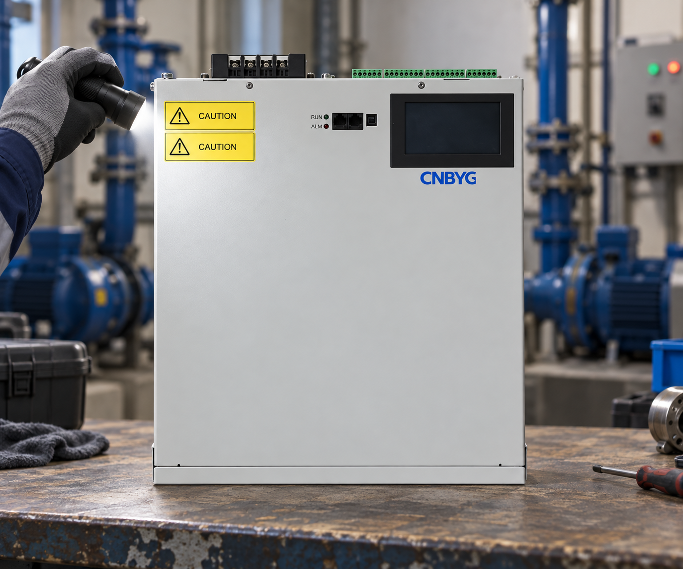
The product-reference image illustrates an unpowered exterior inspection. It does not show approved pump-station wiring, installation clearances or measured performance. Use the selected equipment’s documentation and a site-specific design for those decisions.
Agree a repeatable acceptance and maintenance record
Define the baseline and final test states before installation. Use the same measurement positions, instrument settings and operating combinations where practical. Record any unavoidable change in water demand, pump speed or source configuration so that the comparison is not presented as identical when it is not.
Compare harmonic amperes and the appropriate distortion quantities alongside voltage behaviour, equipment alarms and normal process operation. A lower THDi during a different load state is not sufficient evidence of improvement. Keep the filter’s operational status in the log and preserve periods when it was unavailable instead of removing inconvenient samples.
The AHF performance verification guide provides a supporting framework for the electrical comparison. Acceptance should also confirm that approved duty changeover, standby and backup arrangements remain functional. Harmonic acceptance does not replace pump commissioning, generator acceptance or statutory electrical checks.
For maintenance, retain the accepted baseline, current drawings, model-specific settings and test files. Review changed pump combinations, drive replacements and correction-equipment alarms when the station is modified. A previous successful test remains evidence for its tested configuration, not a guarantee for an altered installation.
Further learning: standards and monitoring
The following NPTEL IIT Delhi lecture, Power Quality: Standards and Monitoring, supports the selection of measurement quantities and acceptance boundaries. It offers general technical education rather than a pump-station installation procedure or supplier endorsement.
Watch Power Quality: Standards and Monitoring
Frequently asked questions
Does the water pump itself create the input harmonics?
The main source may be the drive’s input converter or other nonlinear electrical equipment. Identify the installed converter and measure the feeder; water-flow symptoms alone do not establish harmonic distortion.
Can one unloaded pump test represent the whole station?
No. Capture representative duty combinations, speed ranges and relevant supply arrangements. Document missing operating states and avoid claiming acceptance for conditions that were not assessed.
Should filter capacity equal the total motor current?
Not automatically. Determine the correction task from measured harmonic current and the selected device’s verified functions and limits. Motor nameplate current is not a direct substitute for that assessment.
Can a harmonic filter cure cavitation or all vibration?
No. Cavitation and mechanical vibration need their own process and mechanical evidence. Use electrical event records to investigate an electrical contribution, while keeping the separate diagnoses clear.