Composite Switch Failure Modes and Troubleshooting
Composite switch troubleshooting should start by separating the controller command, the switch’s supply and enable conditions, and the capacitor stage’s actual response. A stage that does not compensate is not automatically a failed composite switch. The fault may involve control wiring, protection, a disconnected capacitor, incorrect measurement or a blocked operating condition. Establish which part of the chain failed before replacing equipment.
This guide covers practical fault classification for a low-voltage capacitor bank. A composite switch can combine electronic and mechanical switching functions, but its exact operating sequence is model-specific. Use the installed switch manual and panel drawings for terminal assignments, diagnostic indications and acceptance tests; never infer those details from a generic photograph.
Identify the installed switch and its role
Record the manufacturer, full model, rated application, control interface and associated capacitor stage. Establish whether the assembly is a composite switch, a conventional contactor or an entirely electronic switching module. These devices can look similar from the cabinet door while requiring different control signals and protection.
For the CNBYG BYFK intelligent composite switch, the real product image can help identify the casing and connection arrangement. It does not justify assuming that another manufacturer’s fault code or sequence applies. Ask for the exact documentation when a label is missing or the assembly revision cannot be established.
Follow the stage circuit through its protective device, switching assembly, reactor if fitted, and capacitor. Note any feedback contact and temperature input. Troubleshooting is faster when the team knows where a command can be interrupted and where operating confirmation comes from. A controller output lamp and a switch indicator may represent different states.
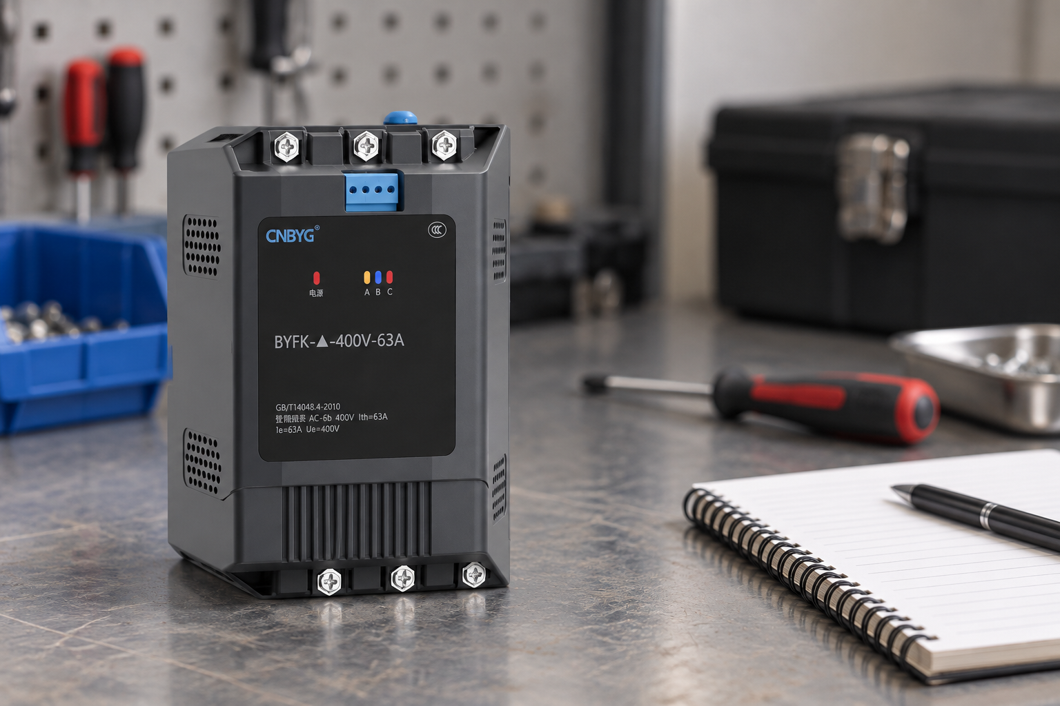
Reference-based illustration. Terminal layout must be checked against the specific product documentation.
Build a fault description before testing
Record the symptom precisely: no operation, delayed operation, missing compensation on one phase, unexpected trip, repeated switching, heating or continued stage current after a removal command. Add the load condition, operating mode and whether the fault occurs after warm-up or immediately on energization. These distinctions help identify an intermittent supply or thermal issue.
Separate observations from interpretations. “Output 3 indicated ON, stage current absent” is more useful than “switch defective.” A loss of stage current could come from an open protective device or capacitor connection. Likewise, a stage that remains energized may reflect a stuck mechanical path, another supply path or an incorrectly interpreted current measurement.
If the installation has changed, record the change first. New capacitors, relocated CTs, altered controller settings and modified control wiring all affect the diagnosis. Compare the current drawing revision with the cabinet; a drawing that no longer matches the installation can lead to confident but incorrect conclusions.
Use a symptom-to-evidence checklist
| Symptom | First distinction to establish | Evidence that supports a next action |
|---|---|---|
| Stage never enters service | Missing command versus blocked switch | Controller log, enabled conditions and approved interface checks |
| Command exists but no stage response | Switch path versus downstream circuit | Protective-device state and isolated continuity checks |
| One phase differs from the others | Measurement error versus phase circuit fault | Phase mapping and approved stage measurements |
| Unit overheats | Local connection versus duty or environment | Inspection, operating counts and ventilation records |
| Stage remains connected | Command logic versus conducting path | Removal command history and verified isolation findings |
| Failure appears only after several operations | Thermal or reconnection dependence | Time-correlated event and stage eligibility records |
This table defines questions to answer, not a sequence of live probing steps. Qualified personnel must choose a safe test method suitable for the actual installation. Indicators can support evidence, but they do not independently prove the condition of every power path.
Check control supply and enable conditions
A missing or unsuitable control supply can prevent operation even if the power circuit is available. Confirm the specified supply source and any interposing relay, fuse or external enable. Compare controller output type with the switch input requirements. A dry contact, an externally powered signal and a communication command are not interchangeable interfaces.
Check what happens during a panel restart. Some systems intentionally block output until measurement is valid or capacitor stages have completed their eligibility period. An apparent delay may therefore be expected behavior rather than a fault. Read the documented restart sequence and do not defeat it to make the stage operate sooner.
Where several stages fail together, investigate shared supplies and common permissives before replacing individual switches. Where one stage is affected, compare its wiring and feedback with a healthy equivalent stage while preserving the approved configuration. Differences can narrow the fault without arbitrary settings changes.
Verifizieren Sie die Messkette
The controller decides whether compensation is required from its voltage and current inputs. Incorrect phase association, CT polarity or ratio can produce a wrong decision even when the switch works correctly. A stage may appear unavailable because the controller sees a leading condition or believes sufficient compensation is already connected.
Use the guide to cURL Too many subrequests by single Worker invocation. To configure this limit, refer to https://developers.cloudflare.com/workers/wrangler/configuration/#limits cURL Too many subrequests by single Worker invocation. To configure this limit, refer to https://developers.cloudflare.com/workers/wrangler/configuration/#limits.
Das cURL Too many subrequests by single Worker invocation. To configure this limit, refer to https://developers.cloudflare.com/workers/wrangler/configuration/#limits cURL Too many subrequests by single Worker invocation. To configure this limit, refer to https://developers.cloudflare.com/workers/wrangler/configuration/#limits.
cURL Too many subrequests by single Worker invocation. To configure this limit, refer to https://developers.cloudflare.com/workers/wrangler/configuration/#limits
cURL Too many subrequests by single Worker invocation. To configure this limit, refer to https://developers.cloudflare.com/workers/wrangler/configuration/#limits OSHA-Regeln für sichere elektrische Arbeitspraktiken cURL Too many subrequests by single Worker invocation. To configure this limit, refer to https://developers.cloudflare.com/workers/wrangler/configuration/#limits.
cURL Too many subrequests by single Worker invocation. To configure this limit, refer to https://developers.cloudflare.com/workers/wrangler/configuration/#limits.
cURL Too many subrequests by single Worker invocation. To configure this limit, refer to https://developers.cloudflare.com/workers/wrangler/configuration/#limits.
Investigate repeated operation and overheating
Count operations by stage and correlate them with production changes. Small rapidly changing loads can make a coarse bank hunt. Excessive duty may arise from stage sizes, settings, measurement error or a mismatch between load dynamics and switching technology. Repeatedly replacing a damaged switch leaves that cause unresolved.
Check the enclosure’s ventilation and ambient conditions against the product requirements. Dust accumulation, blocked airflow and nearby heat sources can change operating conditions. A thermal indication should be investigated using the documented limits, not dismissed because the cabinet feels comfortable externally.
A composite switch’s duty and response are specific to its design. Do not assume that all composite devices provide the same fast compensation as a fully electronic system. Where a load requires another technology, evaluate the complete application rather than changing a delay until the symptom disappears.
Repair and return the stage to service
Replace parts only where the manufacturer permits field service. Use the specified complete assembly when internal switching components are not intended for individual repair. Preserve the original protection and wiring until an approved design change has been assessed. A substitute device must match the control interface, electrical duty and installation constraints.
The acceptance plan should demonstrate correct enable, command, removal and protective blocking behavior. Document the test load and the expected stage response before energization. A single successful operation is weak evidence for a fault that occurs after many cycles or during a hot operating period; the verification should address the original trigger.
For broader context, the reactive-power and harmonic compensation guide connects switching decisions with the rest of the system. The independent NPTEL-Kurs zur Leistungsqualität provides background on electrical disturbances without replacing the switch’s service manual.
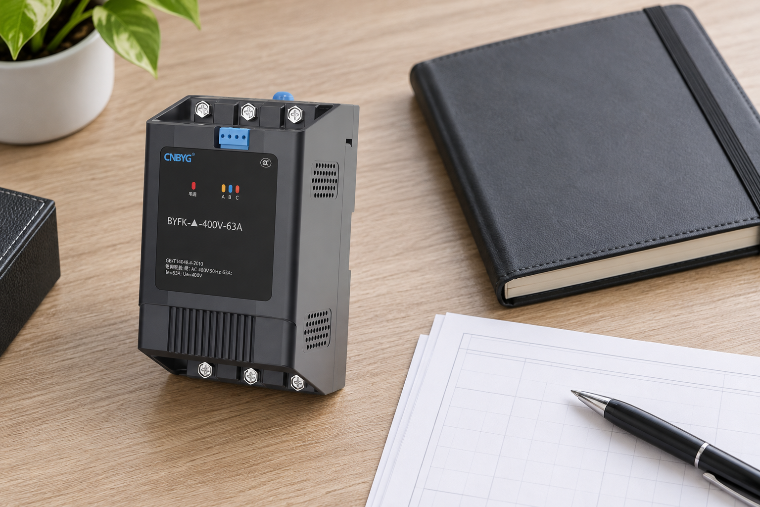
Reference-based maintenance illustration. The actual report should contain measured findings from the installation.
Information to send with a service inquiry
Include the exact model, capacitor stage data, connection diagram, protective device, control supply, controller output type and a description of when the fault occurs. Provide photographs of the intact installation and damage where safely available. Add operating counts, event records and the tests already completed.
State what remains unknown. For example, a unit may show a command indication while downstream current is absent, but no isolated power-path test has yet been performed. That distinction allows the supplier or engineer to request a targeted check instead of assuming that an unverified diagnosis is final.
Weiterbildung
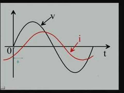
Video-Beitrag – 15 Leistungsfaktor
Häufig gestellte Fragen
Does an ON indicator prove that the capacitor is connected?
No. The indicator may describe a command or internal state. Establish the actual stage response with the approved feedback or measurement method and check the downstream circuit.
Can a composite switch replace any capacitor contactor?
No. Compatibility depends on the control interface, duty, stage configuration, protection and installation. Assess the complete replacement rather than matching only the nominal current.
Should the controller delay be reduced when a stage does not operate?
Not before checking why operation is blocked. Discharge eligibility and protective conditions may intentionally prevent reconnection. A shorter delay can increase stress without repairing the fault.
What is the best evidence for an intermittent fault?
Time-correlated command, feedback, stage-current and operating-condition records. Capture the original trigger and preserve uncertainty where the available records cannot identify the failed path.