Power Factor Correction for Lightly Loaded Transformers
Power Factor Correction for Lightly Loaded Transformers
Power factor correction for a lightly loaded transformer must account for magnetizing current, fixed capacitor stages, cable capacitance and the way the transformer is operated between shifts. The safest result is a stable operating band at the transformer incomer, not a one-time reading close to unity at full production. Measure the transformer boundary, separate no-load reactive demand from process load and prevent capacitors or an SVG from driving the source leading when the load falls.
El Página del producto CNBYG SVG gives the product context for fast, continuously adjustable compensation. Actual settings still require the transformer nameplate, measured voltage, load profile, CT locations and the utility or generator operating rule.
Why a light-load transformer is different
A transformer draws magnetizing current even when its secondary load is small. That current is mostly reactive, so the measured power factor can look poor while the active power is low. A fixed capacitor selected from a peak-load study may then be too large during night operation. The same capacitor kvar that is modest at peak load can become a leading condition when the process stops.
Record kW, kvar, voltage, current, frequency, PF, THD, transformer tap, capacitor state and operating mode. Capture energization, idle, normal production and the lowest permitted load. Note whether the meter is on the transformer primary, secondary main, a feeder or a generator bus; the answer changes with the boundary.

Tabla de decisiones diagnósticas
| Observation at the transformer boundary | Likely cause | First engineering check |
|---|---|---|
| Low PF with very little kW | Magnetizing current dominates the measurement. | Confirm transformer energization and primary/secondary meter location. |
| PF turns leading after production stops | Fixed capacitors or cable capacitance remain connected. | Check minimum-load switching and capacitor step status. |
| PF differs between primary and secondary meters | Different boundaries, CT ratios or transformer losses. | Synchronize meters and mark the single control boundary. |
| PF is unstable after a tap change | Voltage changes alter current and capacitor kvar. | Review tap range, voltage reference and controller deadband. |
| SVG reaches current limit at low voltage | The same kvar requires more converter current. | Check the capability curve at the lowest measured voltage. |
| PF is corrected but THD rises | Current is shared with harmonic or unbalance duties. | Check priority settings and the harmonic spectrum. |
Establish the measurement boundary
Draw a one-line diagram showing the transformer, utility or generator source, main breaker, capacitor bank, SVG, feeders and CTs. State whether the objective is the utility meter, the transformer primary, the transformer secondary or a particular process feeder. An SVG can appear to work correctly at its CT while the utility meter still sees reactive current from another feeder.
Verify CT ratio, phase, polarity, burden and shorting links. Confirm the voltage reference has the same phase order. Compare the SVG display with an independent analyzer during a controlled load change. The Guía de compensación de corriente reactiva SVG explains why a boundary or sign mismatch can look like a failed compensator.
Calculate the no-load and load components
Separate the transformer magnetizing component from the process component. At the lightest normal load, record the average kvar with all switchable capacitor stages open. Then add one known load or feeder at a time and observe the change. This creates a site-specific baseline without assuming a nameplate percentage.
For a three-phase system, the approximate reactive current associated with a measured kvar is:
[
I_Q = \frac{Q}{\sqrt{3} V_{LL}}
]
Use consistent units: Q in var and V in volts. At lower voltage, the required current for the same kvar is higher. The Guía de la tensión de la red y la capacidad de SVG describes why a unit that has spare current at nominal voltage can approach its limit during a voltage sag.
Do not use the transformer’s full kVA rating as the correction target. The target should reflect the measured reactive demand and the permitted operating range. A large correction device may be technically able to force a high PF but can create leading operation, hunting or unnecessary losses when the transformer is energized with little load.

Coordinate capacitors, SVG and tap controls
List every source of reactive current: transformer magnetizing current, fixed capacitors, APFC stages, motor feeders, cable capacitance, UPS systems and generators. Decide which device handles slow base demand and which handles fast changes. A practical arrangement may keep small fixed stages for a predictable base and use an SVG for variable kvar, but only after the lowest-load case is checked.
Set a minimum-load rule. A capacitor stage that is useful at full production may need to open when the transformer is energized but unloaded. If an SVG is used, set a target band and a leading limit rather than commanding an exact unity value at every instant. Define deadband, delay, priority and fallback so two controllers do not chase the same error.
Tap changers require special care. A tap change alters voltage and therefore the current required for the same kvar. The controller should use the approved voltage reference and allow the system to settle before deciding whether another compensation step is required. Record tap position in the acceptance log.
Sizing and selection checklist
- Mark the correction boundary and the utility or generator rule.
- Measure the lowest, typical and peak transformer load.
- Record signed kvar with fixed capacitors open and closed.
- Verify CTs, phase sequence, voltage reference and analyzer agreement.
- Calculate current at the lowest permitted voltage, not only nominal voltage.
- Reserve converter current for harmonic and unbalance duties if enabled.
- Define capacitor minimum-load switching and SVG leading limits.
- Check enclosure heat, clearance, protection and service access.
- Test tap changes, production start, production stop and generator transfer when applicable.
- Save settings, traces, alarms and rollback values.
El Guía de requisitos de instalación de SVG covers airflow, cable entry and service space that can be missed when the transformer room is crowded. The Lista de verificación para la puesta en marcha de SVG can be used to structure the evidence.
Acceptance tests for light-load operation
Acceptance must include the transformer energized with the minimum safe load. Hold that state long enough to observe the capacitor stage status, SVG current, PF sign and voltage. Repeat at normal production, peak production and a controlled load step. Check that the source does not become leading beyond the agreed limit and that the controller does not repeatedly switch stages.
Record synchronized kW, kvar, voltage, current, PF, THD, tap position, capacitor state, SVG output current, temperature and alarms. If the transformer is supplied by a generator, test only under an approved switching procedure because generator voltage regulation and minimum loading can restrict the correction range. The Ingresado en el catálogo de la norma IEC 61000-4-30 provides a reference for power-quality measurement methods; site acceptance still follows the project specification and instrument capability.
Errores comunes a evitar
The first mistake is correcting the wrong meter. A feeder-level SVG may improve a motor feeder while the transformer incomer remains affected by another load. The second is using a peak-load capacitor bank for every operating state. The third is ignoring transformer tap and voltage variation. The fourth is allowing an APFC controller and an SVG to use different signs or different CT boundaries.
Another mistake is treating a low PF at very low kW as a penalty that must always be forced to unity. Check the utility definition and billing interval first. If the source is stable, current is within limits and the agreed PF band is met, a controlled band may be more robust than aggressive correction.
Document the operating envelope
Keep a simple operating envelope with the transformer identification, tap range, minimum and maximum permitted load, capacitor states and the approved PF band. Note the ambient and ventilation conditions when the SVG is tested. If a second transformer can be paralleled, record whether its magnetizing current is included in the same boundary. This prevents a night-shift operator from applying a day-shift setting to a different energized arrangement.
When a setting is changed, retain the old value, the reason, the measured state and a rollback value. Allow the transformer and controller to settle before comparing readings. A short trend through a load transition is usually more informative than a single screen value. Review the envelope after a seasonal production change, a tap-setting change or the addition of a feeder.
Preguntas frecuentes
Why is PF poor when a transformer is almost unloaded?
Magnetizing current remains while active load falls, so reactive current becomes a larger fraction of the total current. Meter location and averaging also affect the displayed value.
Should a capacitor bank correct transformer no-load current?
Only if the measured boundary, utility rule and minimum-load behavior support it. A fixed bank that is suitable at peak load can make the source leading when the transformer is idle.
Can an SVG be used for a lightly loaded transformer?
It can provide adjustable current, but the target band, leading limit, CT boundary and available current must be verified at the lowest voltage and load.
What should be included in the acceptance record?
Include synchronized kW, kvar, PF, voltage, current, THD, tap position, capacitor status, SVG output, alarms and results at minimum, normal and peak load.
Conclusión
Power factor correction for a lightly loaded transformer is mainly a boundary and coordination problem. Measure magnetizing demand, model the lowest-load case, coordinate capacitors and SVG control, and accept the result across the full operating range. A documented target band that avoids leading operation is more useful than a perfect value observed only at peak production.
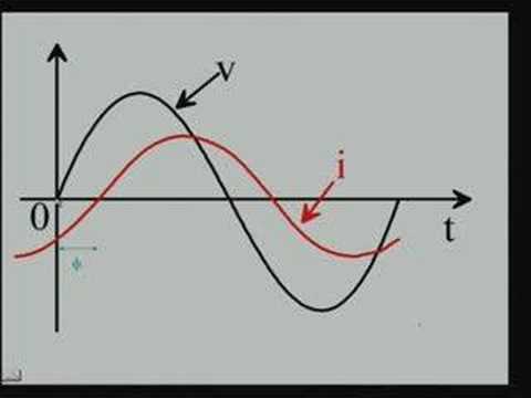
Neutral video: transformer and power-factor background
La conferencia NPTEL que se presenta a continuación proporciona un contexto educativo neutral sobre el factor de potencia y la potencia reactiva. No se trata de una recomendación de compra.