What Is a Static Var Compensator (SVC)?
A static var compensator (SVC) is a fast shunt-connected reactive-power system used to regulate voltage and manage changing capacitive or inductive demand. It typically combines thyristor-controlled reactors, switched capacitor or filter branches, measurement, protection, control, and cooling. Engineers should select an SVC from network studies and a defined operating envelope—not from one nominal Mvar number.
What an SVC Does
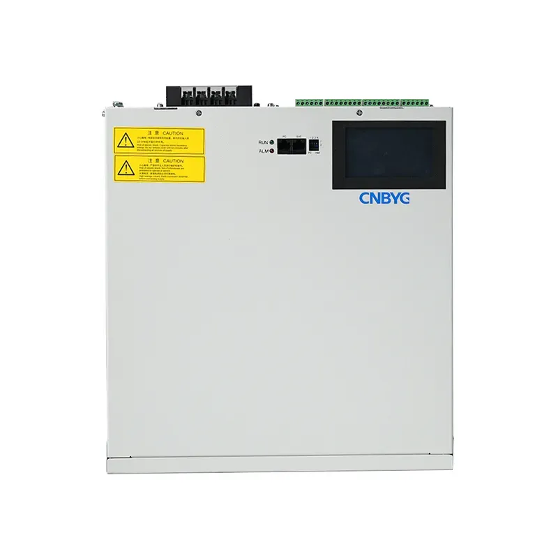
A static var compensator, usually shortened to SVC, is a shunt-connected system that changes reactive power rapidly to control bus voltage, improve power factor, reduce voltage fluctuation, or increase the usable margin of a transmission or industrial network. The word static distinguishes it from a rotating synchronous condenser: the main controlled elements are thyristor valves, reactors, capacitors, filters, transformers, switchgear, and a digital control system. An SVC does not create real energy. It exchanges capacitive or inductive reactive power with the AC system according to measured voltage and the configured control characteristic.
Core Operating Principle
The controller measures bus voltage and other permitted signals, compares them with a reference, and determines the susceptance required from the SVC. A thyristor-controlled reactor varies inductive current by changing the valve firing angle. Thyristor-switched capacitors add capacitive steps with very little intentional delay. Fixed capacitor or harmonic-filter branches may provide a base capacitive output while the controlled reactor absorbs the excess. The combined response can move continuously across much of the operating range. The exact topology, response time, limits, and available output depend on the project design rather than the SVC label alone.
Main SVC Topologies
Common arrangements include a thyristor-controlled reactor with fixed capacitors or filters, abbreviated TCR/FC; a TCR combined with thyristor-switched capacitor branches, TCR/TSC; and smaller thyristor-switched reactor or capacitor variations. A TCR provides smooth inductive control but creates characteristic harmonics that the filter design must address. TSC branches provide stepped capacitive output and are normally switched near a favorable voltage condition. The selected topology balances range, losses, harmonic performance, response, footprint, redundancy, voltage level, and maintenance. A single diagram cannot be reused safely without validating the network and duty cycle.
Voltage Control Characteristic
SVC voltage regulation normally uses a reference voltage, slope or droop, measurement filtering, and capacitive and inductive limits. Droop allows stable sharing with generators, tap changers, capacitor banks, other SVCs, or STATCOMs instead of forcing every controller toward an identical rigid target. When the required susceptance reaches a limit, the SVC cannot maintain the reference indefinitely; available Mvar also changes with bus voltage because passive branch output is voltage dependent. Studies must include weak-grid conditions, transformer taps, credible contingencies, nearby compensation, and control interactions.
SVC Components
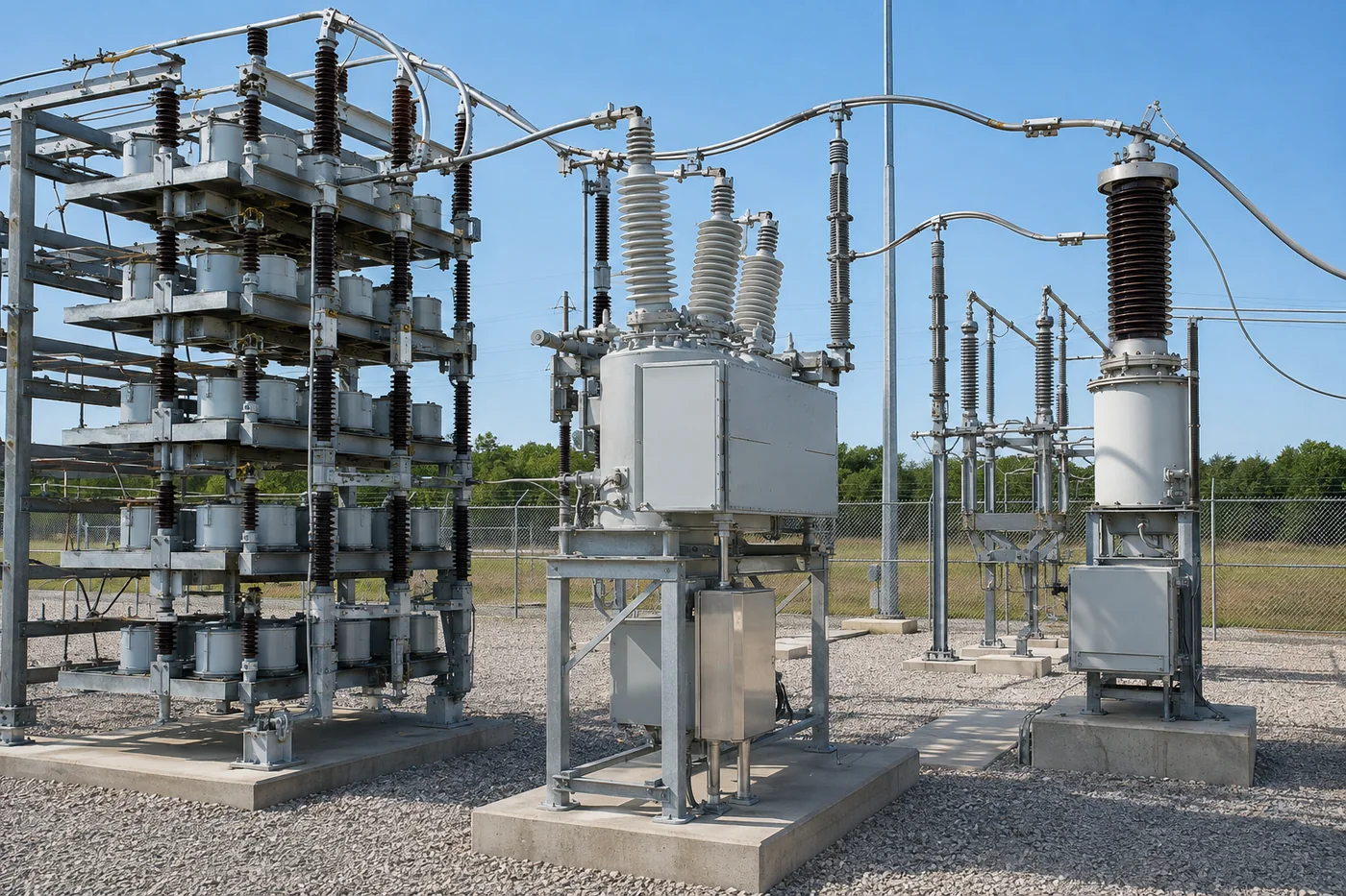
A complete installation may include a coupling transformer, buswork, disconnectors, circuit breakers, surge arresters, current and voltage transformers, thyristor valves, air-core reactors, capacitor and harmonic-filter banks, cooling equipment, protection, control, auxiliary power, building services, fire detection, communications, and grounding. Each subsystem affects availability. Valve cooling or filter branch failure can restrict the usable reactive range even when the controller remains healthy. The specification should define which failures require a trip, which permit automatic derating, and what output remains after the agreed single contingency.
SVC Applications
Utilities use SVCs for dynamic voltage support, transient and oscillatory stability improvement, load-area reinforcement, flicker control, and power-transfer support. Industrial users apply them to electric arc furnaces, rolling mills, mines, large motor systems, and other rapidly changing loads. Renewable and grid-connection projects may use dynamic reactive equipment to meet voltage-control and fault-response requirements. Application determines design: furnace flicker duty, for example, differs from steady transmission voltage support. The required response, unbalance performance, harmonic emission, overload, and redundancy must be stated from measured data and system studies.
SVC Versus STATCOM or SVG
An SVC controls passive reactor and capacitor branches with thyristor valves, while a STATCOM or industrial static var generator uses a voltage-source converter. Converter equipment can retain stronger reactive-current capability as AC voltage falls and can offer a compact continuously controlled response. An SVC may be economical at large ratings and can integrate harmonic filters that supply capacitive vars. Neither technology is universally better. Compare required Mvar across the full voltage range, loss profile, footprint, harmonic performance, overload, cooling, fault behavior, modularity, redundancy, maintenance, and lifecycle cost.
| Pregunta | SVC | STATCOM / SVG | Mechanically switched bank |
|---|---|---|---|
| Controlled element | Thyristor reactor/capacitor branches | Voltage-source converter | Capacitor steps |
| Respuesta dinámica | Fast and continuous/stepped | Fast and continuous | Slower and stepped |
| Low-voltage current capability | Output depends strongly on voltage | Can retain stronger current capability | Falls with voltage squared |
| Engineering focus | Filters, reactors, valves, cooling | Converter, controls, cooling | Switching, resonance, protection |
SVC Versus Capacitor Banks
A mechanically switched capacitor bank supplies discrete capacitive kvar and is well suited to relatively stable demand when its switching speed is adequate. An SVC provides much faster and finer dynamic control and can absorb reactive power when a controlled reactor is included. The tradeoff is greater complexity, losses, controls, cooling, harmonic engineering, and cost. Some substations use both: mechanically switched banks cover slow bulk demand while the SVC manages rapid variation and voltage regulation. Coordination must prevent hunting and keep the SVC away from a continuous limit.
How to Size an SVC
Sizing starts with load-flow, dynamic, harmonic, flicker, and contingency studies. Define the controlled bus, voltage range, short-circuit strength, existing compensation, transformer taps, load and generation profiles, maximum capacitive and inductive requirements, response time, temporary overload, and future cases. State whether the rating is required at the high-voltage bus, transformer secondary, or valve-side connection and whether auxiliary losses are included. A nominal plus-or-minus Mvar value without voltage dependency and operating cases is incomplete. Validate thermal capability and filter loading across the full envelope.
Harmonics and Resonance
TCR current contains characteristic harmonic components, and capacitor or filter branches interact with network impedance. The design process therefore includes harmonic load flow, frequency scan, component tolerances, filter outage cases, system background distortion, transformer impedance, and credible network configurations. Filters must satisfy both harmonic performance and fundamental reactive duty without exceeding capacitor, reactor, resistor, or transformer ratings. Changes elsewhere in the network can alter resonances after commissioning, so the owner should retain study models and review major capacitor, cable, transformer, drive, or generation additions.
Cooling and Environmental Design
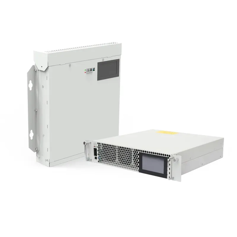
Valve losses and auxiliary equipment require engineered heat removal. Smaller arrangements may use forced air, while high-power thyristor valves often use closed deionized-liquid cooling with redundant pumps and external heat exchangers. Ambient temperature, altitude, dust, salt, corrosive gases, solar load, building ventilation, acoustic limits, water quality, and station-service reliability affect available output. Specify the full-output duty and the permitted output after a fan, pump, cooler, or auxiliary feeder failure. Temperature, flow, conductivity, leak, and pressure signals should support alarms, derating, and trips.
Protection and Control Coordination
Protection may cover valve overcurrent, branch overcurrent, capacitor unbalance, reactor faults, transformer differential and restricted earth fault, bus faults, cooling failure, overtemperature, overvoltage, undervoltage, and control or communication failure. Settings must coordinate with system protection and the SVC control limits. The controller should transfer between modes or limit output without creating an unstable voltage step. Cybersecurity, time synchronization, event recording, disturbance records, remote access, and change control belong in the specification because diagnosis often depends on aligned electrical and control data.
Pruebas de puesta en marcha
Commissioning progresses from inspection and individual equipment tests to interlock checks, valve and cooling tests, protection injection, closed-loop control tests, staged energization, harmonic measurements, and performance demonstration. Verify polarity and phase mapping before automatic control. Demonstrate capacitive and inductive limits, voltage characteristic, response time, mode transfer, alarms, derating, redundancy, and loss-of-auxiliary behavior under safe test conditions. Record bus voltage, Mvar, valve current, branch current, firing angle, temperatures, cooling data, harmonic spectrum, and controller events as the reference baseline.
Maintenance and Troubleshooting
Trend output, voltage error, branch currents, valve temperature, cooling flow and conductivity, filter condition, alarms, switching operations, and harmonic levels. Inspect reactors, capacitors, connections, bushings, arresters, cooling equipment, air filters, pumps, valves, hoses, deionizers, fans, and building systems at intervals based on duty and environment. A rising temperature at the same Mvar and ambient can reveal fouling or reduced flow. Repeated limit operation may indicate that the network has changed or that slow compensation is unavailable. Safety procedures must address isolation, stored charge, induced voltage, and grounding.
Information to Include in an RFQ
Provide one-line diagrams, controlled bus, system voltage and frequency, short-circuit levels, transformer data, load and generation profiles, existing compensation, background harmonics, voltage-performance criteria, capacitive and inductive range versus voltage, response time, overload, unbalance, flicker limits, contingencies, ambient and altitude, pollution, cooling utilities, station service, redundancy, communications, cybersecurity, tests, standards, documentation, training, spares, and lifecycle requirements. Require suppliers to identify exclusions, model assumptions, guaranteed losses, available output after failures, harmonic filter duties, and the boundary between SVC equipment and site works.
Related Technical Guides
Continue with SVC cooling and derating, SVG capacity selection, substation capacitor-bank applications, y CNBYG static var generator products.
Preguntas frecuentes
What is the main purpose of an SVC?
Its main purpose is fast reactive-power control for voltage regulation, power-factor support, flicker reduction, or network stability.
Is an SVC the same as a STATCOM?
No. An SVC controls reactor and capacitor branches with thyristors; a STATCOM uses a voltage-source converter.
Can an SVC absorb reactive power?
Yes, when its topology includes sufficient controlled inductive range, such as a thyristor-controlled reactor.
Does an SVC remove all harmonics?
No. Its filters are engineered for defined emissions and network cases; background harmonics and resonances still require study.
How is SVC rating specified?
State capacitive and inductive Mvar across the required bus-voltage range, operating cases, overload, response, losses, and contingencies.
Referencias
- IEEE 1534 — Static Var Compensator Functional Specification Guide
- U.S. Department of Energy — Flexible AC Transmission Systems
Further Learning