

“Redundant APF” can mean spare installed current, parallel modules, a maintenance bypass, or a tested failover sequence. Those are not interchangeable. A defensible plan defines the electrical boundary, the isolation device, the CT reference and the restoration test before a supplier is asked to promise continuity.

Define redundancy in electrical terms
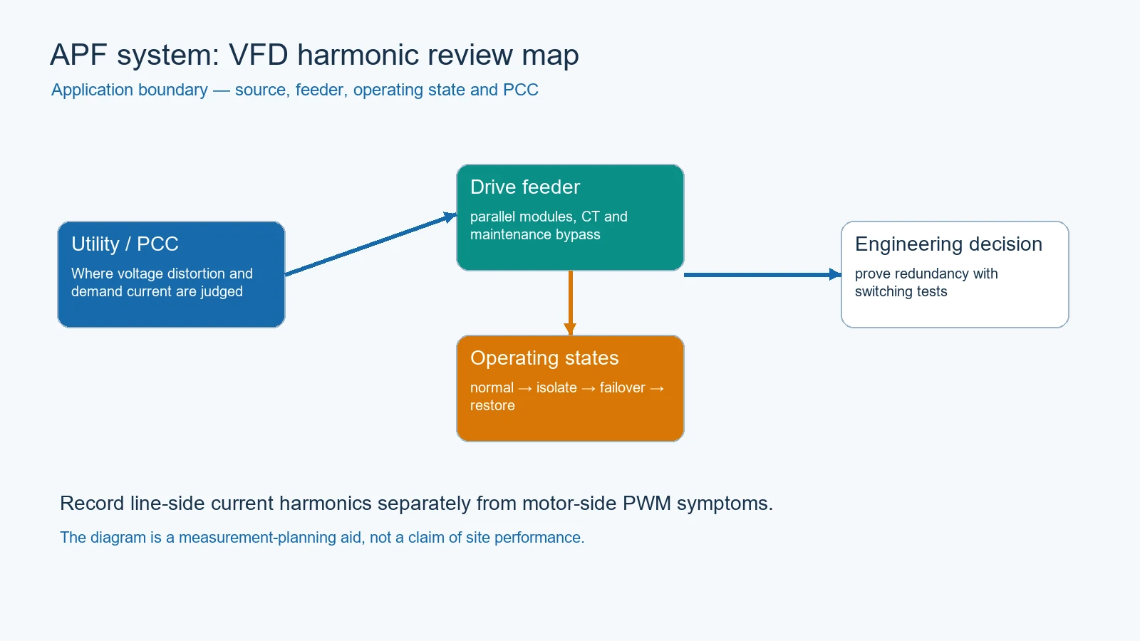
Write down the required service boundary first: a drive feeder, a main bus or the PCC. Then define whether redundancy means spare installed current, parallel modules that share a load, a bypass that keeps the load energized, or a tested failover sequence. A spare module that is not isolated, cooled and commissioned is not proven redundancy.
Draw the normal, isolate and restore states
The one-line should show the APF connection, CT reference, protective devices, module isolation, maintenance bypass and control interlocks. TCI and Delta manuals show why CT direction, qualified installation and startup checks are operational requirements. MTE’s multiple-drive note also shows that grouping and light-load bypass conditions can change the correct arrangement.
| State | Required evidence | Release condition |
|---|---|---|
| Normal | module status, CT feedback, feeder spectrum | all operating modules stable |
| Module isolate | open/closed devices and alarm log | remaining path safe and controlled |
| Maintenance bypass | interlock and protection state | bypass does not create an unreviewed path |
| Failover / restore | timed sequence and post-event spectrum | boundary remains within the agreed design target |
Test failover without inventing capacity
A commissioning plan should state the load state, which module is isolated, who controls the switching, what alarms are expected, and what values are read back. Delta’s manual describes modular coordination and CT-based detection for its product; that is evidence for the checklist, not evidence that a CNBYG model has the same architecture.
Evidence to request from a supplier
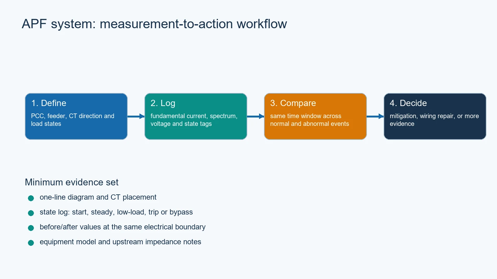
- Model-level single-line and module topology.
- Continuous, standby and maintenance-bypass current paths.
- CT location, direction, ratio and sharing logic.
- Isolation, interlock, protection and cooling requirements.
- Failover test steps, alarm behavior and restoration record.
- Limits: what the supplier does not claim when a module is unavailable.
Conditional APF recommendation after the bypass design is proven
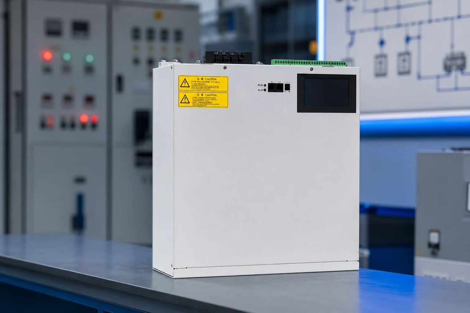
La CNBYG AHF/APF product path is a conditional next step for a project that has already defined the bypass and failover evidence. CNBYG’s public materials do not establish a model-level redundancy architecture, so this article makes no claim of hot-swap, N+1 capacity, uptime or automatic failover. Ask CNBYG for the missing datasheet, schematic and test record before specifying the system.
Utilisez le Pilier du système de qualité de l'énergie, parallel APF load-sharing and CT commissioning article et CT placement and wiring article as the next internal path.