Configurações do Controlador Automático do Fator de Potência: Guia de Comissionamento
Automatic power factor controller settings should be commissioned from measured system conditions, not copied from another panel. Start by confirming the current-transformer ratio and direction, nominal voltage and frequency, capacitor step sizes, switching sequence, target power factor, connection and discharge delays, and alarm thresholds. Then test the controller through representative low, normal, and peak-load periods while watching measured kvar, step status, voltage, current, and leading or lagging indication. A correct setting plan prevents hunting, unnecessary switching, overcorrection, and misleading alarms. The procedure below is a field checklist for qualified personnel; the controller manual, capacitor discharge requirements, protection study, harmonic assessment, and local electrical rules remain controlling documents.
- What the controller is actually deciding
- Pre-energization checks
- Program the measurement foundation first
- Map capacitor stages and switching sequence
- Set target, delays, and control band
- Commission under changing load
- Troubleshooting unstable behavior
- Handover records
- Decision table
- Sources and further learning
- Perguntas frequentes
What the controller is actually deciding
An automatic power factor controller does not create reactive power. It measures electrical quantities and decides when available capacitor stages should be connected or removed. The decision may use reactive-power demand, phase angle, current, voltage, switching history, and programmed timing. That distinction matters during commissioning: a controller can display a plausible power factor while acting incorrectly if the CT polarity, phase reference, or step map is wrong. Treat the display as one observation, not proof. Compare it with an independent meter at the same measurement point and record the load state. The controller also needs a realistic model of the bank. A panel with unequal steps cannot be commissioned as if every output represented the same kvar. Likewise, an output assigned to a failed contactor or blown fuse must not remain available in the step sequence. The goal is stable correction across the operating envelope, not a perfect number during a five-minute test.
Pre-energization checks
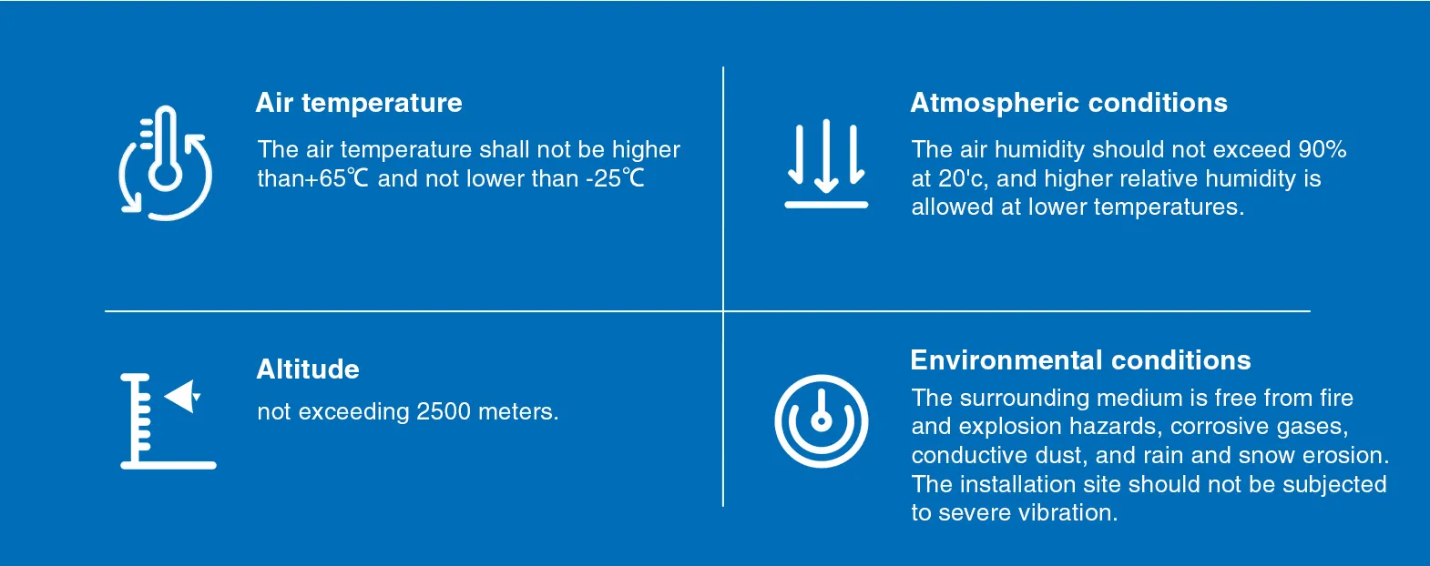
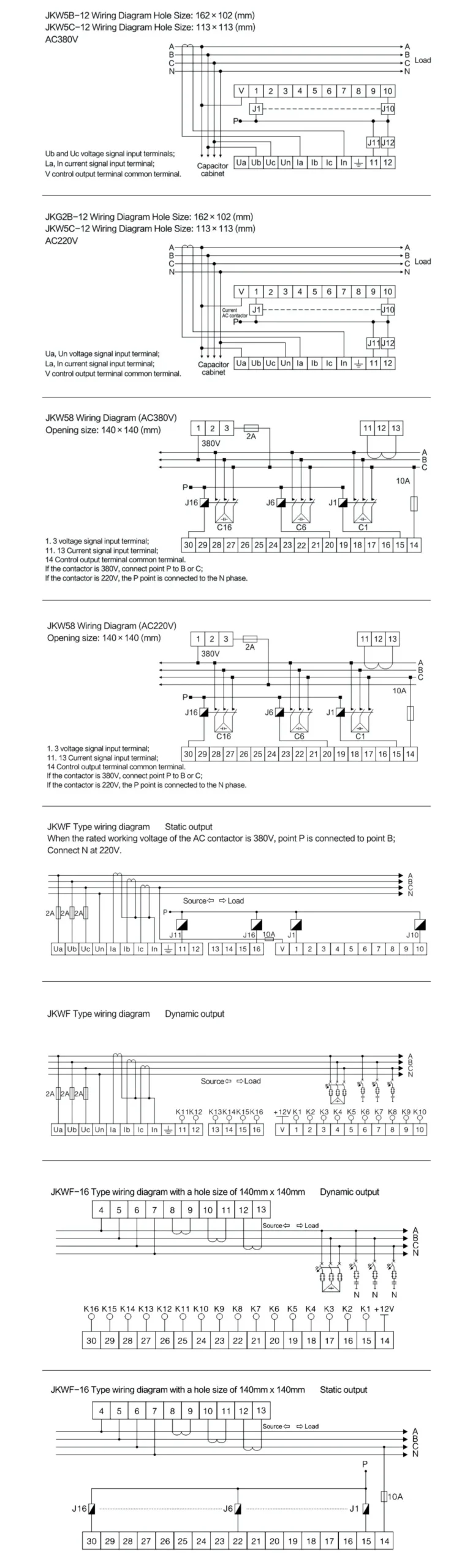
Work from the single-line diagram and approved panel drawings. Confirm the CT is on the intended feeder, its primary orientation points toward the load as required by the controller design, and its secondary lands on the correct terminals. Verify that the voltage reference corresponds to the expected phase relationship. Inspect control fuses, output wiring, contactor or switch coils, reactor and capacitor nameplates, protective-earth continuity, ventilation, and physical clearances. Each capacitor stage needs a safe discharge path and a switching device rated for the duty. Lock out and verify absence of voltage before touching conductors. OSHA's electrical work-practice rule requires de-energization unless a specific exception applies; commissioning convenience is not an exception. Record the initial state before energization so later discrepancies can be traced rather than guessed.
Program the measurement foundation first
Enter the CT primary and secondary ratings exactly as installed. If the controller accepts a ratio rather than two values, calculate it from the nameplate and check the manual's convention. Set system voltage, frequency, wiring mode, and phase selection. After energization, compare displayed current, voltage, active power, reactive power, and power factor with an independent instrument. A near-zero current under a known load, a leading indication on a clearly inductive load, or a negative active-power reading usually points to measurement wiring or phase-reference problems. Do not compensate for those problems by changing target power factor or reversing logic in software. Fix the measurement chain, repeat the comparison, and document the final phasor relationship.
Map capacitor stages and switching sequence
List each physical stage by output number, kvar rating at actual bus voltage, switching device, reactor status, fuse or breaker, and discharge arrangement. Program the controller with that real sequence. For equal steps, rotational switching can spread wear. For unequal steps, progressive or optimized selection may reduce overshoot, but only if the entered ratios are correct. Manually command one stage at a time where the controller and site procedure permit. Confirm the intended contactor or composite switch operates, the stage current is balanced, and the measured reactive-power change has the expected direction. A mismatch between commanded and actual stage is a wiring defect, not a tuning issue. Disable unavailable stages until repairs are complete.
Decision table
| Setting group | Prova necessária | Commissioning check | Do not use as a shortcut |
|---|---|---|---|
| Transformador de corrente e referência de tensão | Drawing, CT nameplate, phase identification | Compare V, A, kW, kvar and PF with an independent meter | Changing logic to hide reversed polarity |
| Stage map | Capacitor/reactor nameplates and output wiring | Command each stage and confirm balanced current and kvar direction | Assuming all outputs have equal kvar |
| Target and control band | Utility requirement and light-load behavior | Verify no persistent leading PF | Automatically setting the target to 1.00 |
| Switching delays | Controller, switch and capacitor documentation | Observe full connect, disconnect and discharge sequence | Using very short delays to improve display response |
| Alarms | System study and equipment ratings | Test or simulate according to approved procedure | Copying alarm limits from another panel |
Set target, delays, and control band
Choose a target that meets the facility or utility requirement while leaving margin against leading power factor during light load. A universal 1.00 target is not automatically best. The connection delay should reject short load transients; the reconnection delay must respect capacitor discharge and switching-device requirements. The disconnection delay should remove excess capacitance without causing rapid oscillation around the threshold. If the controller offers a C/k, response value, or kvar threshold, derive it using the manufacturer's method and the smallest effective step. Watch at least several complete operating cycles. Repeated add-remove behavior indicates the step is too large for the changing demand, the dead band is too narrow, the delay is too short, or the measurement is unstable.
Commission under changing load
Test more than one snapshot. Record a no-production or light-load period, a stable normal-load period, and at least one major load transition. At each point note active power, reactive power, power factor, voltage, current, total harmonic distortion if available, connected stages, and alarm state. Verify that inductive demand causes appropriate connection and that falling demand causes orderly removal before the site becomes persistently leading. If nonlinear loads are significant, do not assume capacitor correction solves distortion. The IEEE 519 framework evaluates harmonic performance at the point of common coupling, and a harmonic study may be needed before adding or reconfiguring capacitors. Controller commissioning and harmonic compliance are related but separate tasks.
Troubleshooting unstable behavior
When stages hunt, freeze the urge to lengthen every timer. First check whether the measured kvar actually crosses the thresholds, whether a large cyclic load is driving the change, and whether a stage returns the expected kvar. A weak capacitor, open fuse, failed coil, welded contact, incorrect step ratio, reversed CT, or phase mismatch can all mimic a settings problem. Compare command status, auxiliary contact, stage current, and reactive-power change. If a stage is commanded on but produces no balanced current, isolate and inspect it. If current appears but reactive power moves the wrong way, recheck phase and CT references. Settings should describe a healthy physical system; they should not conceal failed equipment.
Handover records
Save the final parameter export or photograph each settings screen, but also preserve the reasoning behind the values. The handover sheet should identify drawing revision, CT ratio and location, phase reference, stage map, target, control band, all timers, alarm limits, firmware or controller version, test instruments, test date, and representative load records. Add a trigger for revalidation after transformer changes, major VFD additions, capacitor or reactor replacement, utility tariff changes, or repeated unexplained alarms. A repeatable record turns future troubleshooting into comparison instead of reconstruction.
How this topic connects to CNBYG equipment
This guide supports specification and commissioning discussions for the Reactive power compensation controller product line. Product data must be checked against the actual system voltage, load profile, harmonic measurements, protection design, environmental conditions, and applicable project requirements. Share a single-line diagram and representative measurements before requesting a model recommendation.
Related CNBYG engineering guides
- how to calculate power factor
- calculate reactive power from plant measurements
- understand a conventional reactive power compensator
Sources and further learning
O U.S. Department of Energy motor-driven systems guide explains where fixed and automatically switched power-factor correction can fit industrial load patterns. OSHA 1910.333 provides the U.S. baseline for de-energizing and electrical work practices. IEEE 519 is the standards-body reference for harmonic control at the point of common coupling. Apply the current editions and local requirements for the project.
Further learning: MIT OpenCourseWare Lecture 4: Power Factor. The MIT lecture explains power factor and distortion; it does not replace project-specific equipment instructions.
Perguntas frequentes
What power factor should an APFC controller target?
Use the facility or utility requirement and maintain margin against leading operation at light load. The correct target depends on the system and should not be copied blindly.
Why does an APFC panel keep switching stages on and off?
Common causes include a narrow control band, short delays, an oversized smallest step, rapidly varying load, wrong step ratios, failed stages, or unstable measurement wiring.
Can controller settings fix harmonic distortion?
No. A controller manages reactive compensation stages. Harmonic distortion requires measurement and a separate engineering assessment; capacitors can interact with network impedance.
When should the settings be reviewed again?
Review after major load or transformer changes, capacitor or reactor replacement, protection changes, repeated alarms, or changes to utility power-factor requirements.
Final engineering note: Treat formulas and checklists as screening tools. Installation, protection, commissioning, and energized testing must be performed by qualified personnel using approved drawings, product manuals, studies, and site safety procedures.