How to Select a Low-Voltage Power Capacitor
Select a low-voltage power capacitor from the measured system voltage, required kvar, connection, harmonics, switching duty, temperature, protection and applicable product requirements. Do not choose only from the nominal bus label or a desired power factor. A suitable capacitor must deliver the intended reactive support without excessive voltage stress, resonance, inrush, heat or leading operation at light load.
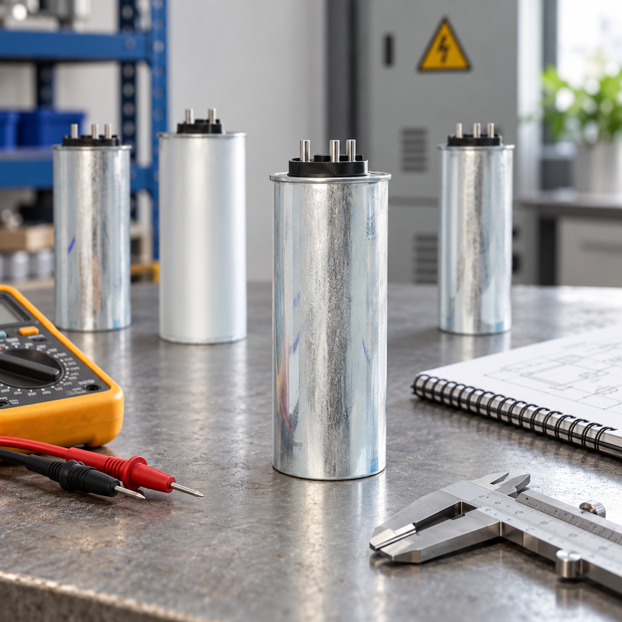
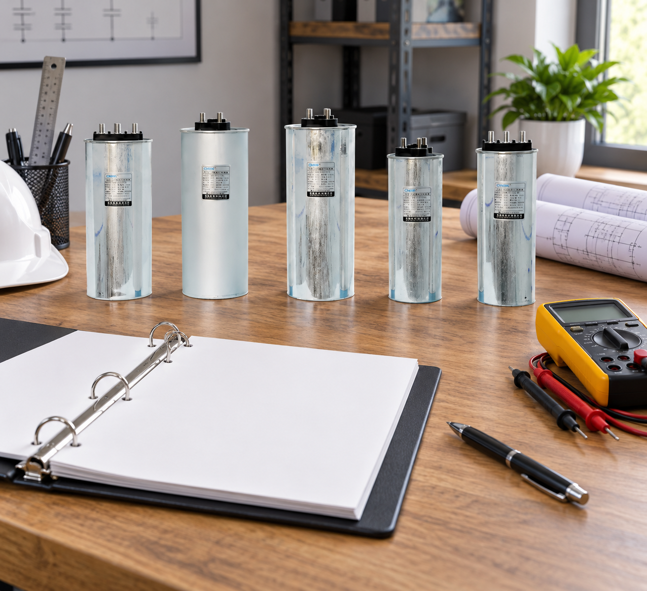
Земля CNBYG cylindrical BSMJ power capacitor family provides context for dynamic compensation when a fixed capacitor is not enough. Final capacitor selection belongs to the electrical design, manufacturer data and site study.
Define the application first
Mark the capacitor connection on the one-line diagram and state whether the bank is at a motor feeder, MCC, transformer secondary or PCC. Record nominal line-to-line voltage, frequency, phase arrangement, transformer taps, voltage tolerance, short-circuit level and available fault current. List motors, VFDs, rectifiers, welders, UPS systems, solar inverters, EV chargers and other harmonic sources.
Measure kW, signed kvar, voltage, current, true PF, displacement PF, THD, harmonic orders, temperature and load state. Include minimum, normal, peak, start, stop and transition conditions.
Selection table
| Selection factor | Вопрос | Доказательство |
|---|---|---|
| Напряжение | What maximum continuous and transient voltage can occur? | Voltage study, tap range and measurement. |
| kvar | What net reactive support is required at the boundary? | Measured kW, kvar, PF and target band. |
| Соединение | Does each capacitor see the intended phase voltage? | Approved single-line and connection drawing. |
| Гармоники | Can the bank resonate or overheat? | Harmonic spectrum and reactor study. |
| Switching | How often will stages switch and what inrush occurs? | Controller, contactor or thyristor settings. |
| Окружающая среда | What ambient, enclosure and cooling apply? | Layout, ventilation and manufacturer limits. |
| Защита | Are fuses, breakers, discharge and alarms coordinated? | Protection study and commissioning tests. |
Calculate the required kvar
Estimate net correction from measured active power and the initial and target PF:
Q_c = P × [tan(arccos(PF₁)) − tan(arccos(PF₂))]. Q_c is required compensation in kvar, P is active power in kW, and PF₁/PF₂ are initial and target displacement power factors. Apply the formula only to the defined boundary and appropriate operating condition.
Use consistent units and the same boundary. Subtract existing signed capacitor kvar and include transformer magnetizing demand. Calculate separate states for minimum, normal and peak load. A bank sized at peak production may be excessive when the process stops.
Земля capacitor-bank safety requirements explains why voltage affects current for a given kvar. If the load changes quickly, use steps or dynamic support rather than one large fixed stage.
Check harmonics, reactors and switching
Capacitors can interact with transformer and system inductance. Review harmonic voltage, current and resonance before connecting the bank. If a detuned reactor is used, confirm tuning, continuous current, temperature and the resulting capacitor voltage. Do not copy a reactor percentage from another plant.
Check contactor or thyristor switching, inrush, minimum on/off time, discharge, fuses and breaker coordination. The the purpose of reactors in capacitor banks provides related measurement-boundary checks. The Руководство по установке SVG covers cooling and access.
Select steps and control behavior
Choose step sizes that match the load variation. Define a deadband, delay, minimum load, leading limit and fallback. If an SVG, APFC relay and inverter share a boundary, assign one primary controller in each mode. For generator or solar export, review the target separately.
Земля Список задач по настройке SVG can structure phase, CT, protection and alarm tests. The capacitor-bank maintenance checklist helps preserve settings and temperature records.
Practical selection sequence
- Mark the capacitor boundary and connection.
- Confirm voltage, frequency, phase and tap range.
- Measure kW, kvar, PF, voltage, current and harmonics.
- Calculate net kvar for minimum, normal and peak states.
- List existing capacitors, reactors and compensators.
- Check resonance, inrush, switching, temperature and protection.
- Select voltage, kvar, step size and control hierarchy.
- Test starts, stops, minimum load and peak load.
- Record voltage, current, THD, alarms and temperature.
- Save as-left settings and review triggers.
Common mistakes
Do not select from nominal voltage alone. Do not ignore connection or harmonics. Do not use nameplate kW instead of measured load. Do not leave a fixed stage connected at light load without checking leading kvar. Do not assume a detuned reactor removes every resonance risk. Do not omit discharge, protection or cooling.
Record the selection assumptions
Keep the selected voltage, frequency, connection, kvar, step size, reactor arrangement, temperature class, protection and discharge data in one record. Add the measured voltage range, harmonic spectrum, transformer tap and minimum-load state. If a value is estimated, mark the estimate and schedule the measurement before final energization. This prevents a replacement capacitor from being ordered from an old nominal label after the system has changed.
Compare the selected kvar with the measured signed kvar at minimum, normal and peak load. Confirm that the bank does not create leading PF when the process stops and that the controller can block a stage. If the plant operates on a generator, solar inverter or battery, repeat the check for each source mode. The same fixed stage can be acceptable on utility power and inappropriate on a lightly loaded generator.
For procurement, request the complete data sheet, drawings, declarations, temperature and harmonic limits, reactor details, discharge method, protection recommendations, switching duty and maintenance instructions. Keep the approved alternative and the reason for rejection of other ratings. During commissioning, test each stage, record voltage and current, verify protection and save the as-left controller settings.
Review the selection after a new VFD, rectifier, UPS, transformer, solar inverter or EV charger is added. A new harmonic source can change current, resonance and temperature without changing the nominal bus voltage. The maintenance record should identify the next review trigger and the responsible person.
Verify the as-built connection
Before energization, compare the installed connection with the approved drawing. Confirm phase labels, neutral treatment, reactor location, discharge circuit, CT direction, fuse or breaker settings and the stage order. A correct component on the wrong side of a CT can make the controller increase rather than remove reactive current. A correct bank with a different transformer tap can also deliver a different kvar than the design estimate.
Use an independent analyzer for the first stage test. Record the voltage, current, signed kvar, PF, THD, temperature and alarm state before and after switching. Wait for the stage to settle before comparing. Repeat after the load changes and at the minimum normal load. If a stage is blocked, record the reason instead of treating the missing kvar as a failed capacitor.
The selection should also state what happens when the target cannot be reached. The controller may relax the PF band, preserve harmonic priority, block a stage or alarm at a current limit. Operators need that behavior before a production change occurs. Keep the previous setting and rollback value, and define the person who can approve a new stage size. This is particularly important when the plant switches between utility, generator, solar export and battery modes.
At handover, give maintenance the approved drawing, calculation inputs, capacitor and reactor data, protection settings, discharge procedure, stage sequence, temperature limits and review triggers. The next reviewer should be able to determine whether a new VFD, transformer tap or load schedule invalidates the selection without rebuilding the entire study.
Keep a clear distinction between the calculated net kvar and the bank’s nameplate kvar. Existing capacitors, transformer magnetizing current and other compensators can change the net result. If the plant has rapid load changes, show which portion is handled by fixed steps and which portion is handled dynamically. This makes future troubleshooting faster and reduces the risk of adding a second controller with a conflicting boundary.
The selection record should also show the maximum current and voltage used for the check, not only the nominal values. Keep the approved step sequence, leading block, alarm behavior and rollback beside the data sheet so the bank can be serviced without guessing.
If the bank cannot meet the requested target at the lowest voltage, record the limitation and choose whether to relax the band, reserve current for harmonics, add capacity or change the boundary. Do not conceal an unavailable target by changing the meter definition.
Keep the decision with the as-left record.
Include the reviewer and test date.
Keep the raw analyzer file.
Record the final alarm state.
Keep the test conditions.
Keep the approved drawing.
Attach the calculation file.
Keep the source measurements.
Keep the as-left settings.
Keep the signed acceptance sheet.
Source boundaries for capacitor selection
IEC 60831-1 identifies the standards family for self-healing low-voltage shunt capacitor units and banks. Use the applicable requirements and the installed product documentation; a standards catalogue summary is not an acceptance procedure. OpenStax explains capacitor reactance and AC behaviour, which underpin the voltage, frequency and capacitance relationships. For reactor-equipped banks, assess the matched branch and harmonic duty rather than treating the capacitor as a bare element.
Правила OSHA по электробезопасности при проведении работ address hazardous stored energy and verification in their jurisdiction. Qualified personnel must follow the approved local isolation and discharge procedure; capacitor selection does not establish that an existing bank is safe to access.
Часто задаваемые вопросы
What is the first capacitor-selection input?
Define the connection boundary, voltage, frequency, load profile and measured net kvar before choosing a product rating.
Are larger kvar steps always better?
No. Large steps can cause overcorrection and switching transients. Match steps to load variation and use a stable deadband.
When is a dynamic SVG preferable?
When reactive demand changes quickly, harmonics share current, or fixed stages would become leading at light load.
What proves the selection is safe?
Measured voltage, current, harmonics, temperature, protection, switching and PF results across minimum, normal and peak states.
Заключение
Low-voltage power-capacitor selection is a system study, not a nominal-voltage lookup. Match voltage, kvar, connection, harmonics, reactors, switching, environment and protection to measured operating states, then test the bank across the full load range.
Educational video: capacitor fundamentals
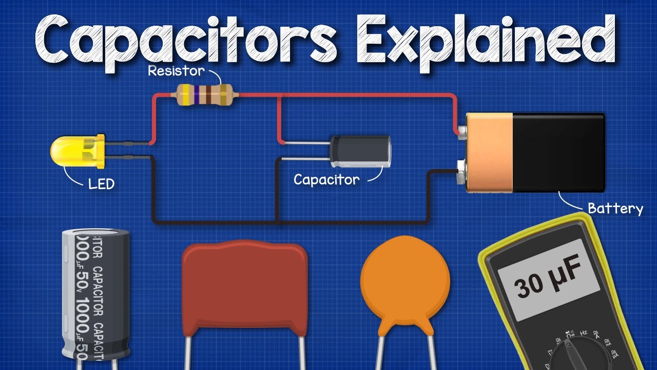
The Engineering Mindset explains capacitor charge storage and basic behaviour. Small-component demonstrations are conceptual background, not an industrial testing or discharge procedure.