แรงดันไฟฟ้าต่ำในคอยล์คอนแทคเตอร์ตัวเก็บประจุ: วิธีวินิจฉัยอาการหน้าสัมผัสสั่นอย่างปลอดภัย
Capacitor contactor coil undervoltage can cause incomplete pickup, repeated opening and closing, and damage to the switching assembly. The useful diagnosis is to establish whether the contactor receives a stable command and the correct voltage during the actual pickup event. A normal reading taken after the event can miss the cause. Separate supply voltage loss, resistance in the control path, repeated controller commands, and mechanical obstruction before replacing components. This guide addresses control-circuit investigation in low-voltage capacitor panels; it does not provide a universal minimum coil voltage or authorize energized work.
Why chatter needs a prompt investigation
A capacitor contactor is an electromagnetic switching device with a control circuit and a separate power circuit. A small AC hum can be a characteristic of the magnetic assembly, but repeated visible movement or repeated closure is a different symptom. Do not classify both simply as noise. Record whether the sound is steady, whether the armature moves repeatedly, and whether the stage indication changes with it.
In capacitor switching, each unintended closure is also another switching event. The duty of the main contacts and the surge-limiting assembly therefore matters alongside the coil condition. A burnt resistor block does not, by itself, prove that the capacitor was oversized. A successful repair should explain the initiating condition and determine which components were subsequently damaged. See the separate guide to capacitor contactor resistor failure for that component-specific assessment.
Establish a safe measurement plan first
Prepare the single-line diagram, the control schematic, the exact installed coil designation, and the panel isolation procedure. Main bus voltage and coil voltage are different quantities. A panel supplied at one voltage may use a control transformer or another source for its switching coils. Identify all supplies, including remote control circuits that remain powered when the main disconnect is open.
OSHA 1910.333 addresses deenergization, lockout, verification, and hazardous stored electrical energy. Apply the rules applicable to the installation and its jurisdiction. Capacitor discharge and absence-of-voltage verification belong in the approved work procedure. A controller OFF command is not an isolating device. Any energized diagnostic measurement requires qualified personnel and the site’s electrical safety controls; this article is a diagnostic framework rather than a live-testing instruction.
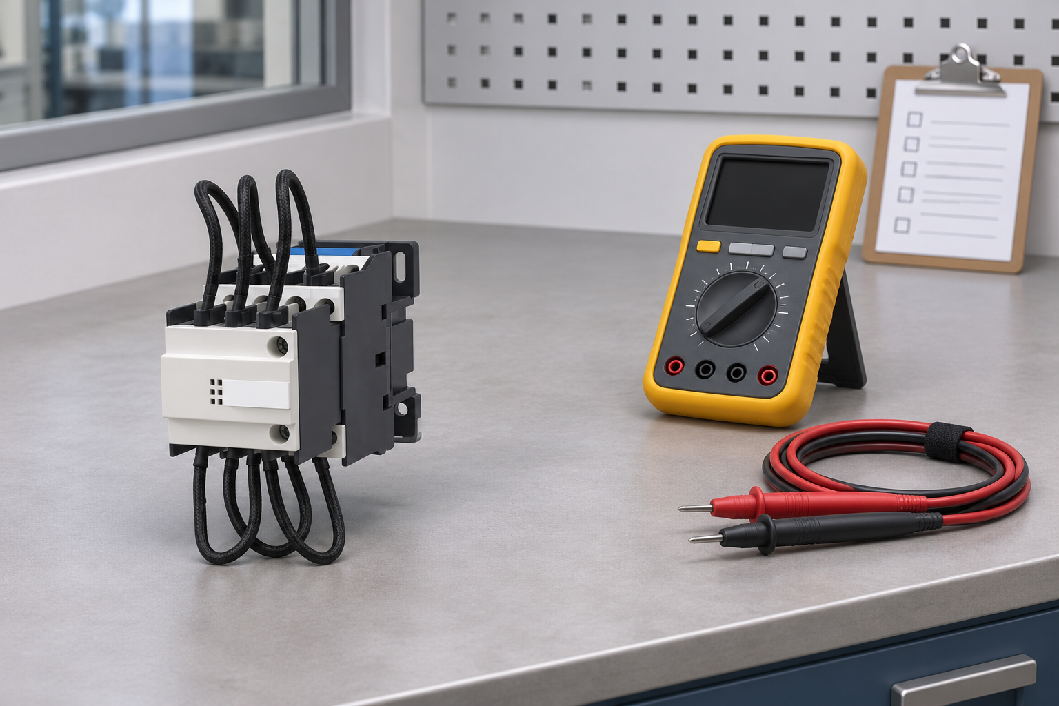
Use existing approved monitoring points or arrange instruments during an isolated condition where the procedure permits. Choose equipment with suitable voltage and measurement-category ratings. Record the instrument’s capture mode and limitations: a slow display may show an acceptable average while a short pickup-related dip occurs between updates. Do not create a suspected fault deliberately by repeatedly cycling a damaged capacitor stage.
Read the installed coil information correctly
Record rated control voltage, AC or DC operation, frequency where applicable, and the manufacturer part identification. Similar-looking contactors can have different coils. An invoice description or a panel drawing may describe the intended component while the installed unit differs. A readable nameplate photograph and the approved bill of materials should agree before the diagnostic limits are selected.
CNBYG GJ19 switching capacitor contactor page describes a capacitor-duty assembly with current-limiting contacts and resistors. Its ordering information distinguishes coil supply voltage and frequency. Confirm the exact delivered model and manual, particularly where catalogue naming differs between a product family heading and individual model designations. This guide does not extend one catalogue operating range to every coil or installation.
Pickup conditions, holding conditions, and release conditions are not interchangeable specifications. A contactor that remains closed during a moderate dip may still fail to close correctly if the same voltage is present at pickup. Likewise, an instrument reading with the coil disconnected says little about the supply’s ability to deliver pickup demand. Compare the observed event with the relevant manufacturer operating condition, including temperature and frequency boundaries.
Separate five fault paths before selecting a remedy
The following table is a diagnostic decision aid, not a table of universal acceptance limits. Its categories describe observations that must be confirmed against the actual schematic and component documentation. Preserve the event timing so that the control command, source voltage, and coil voltage can be compared meaningfully.
| Observed evidence | Plausible fault path | Next useful check | Remedy boundary |
|---|---|---|---|
| Control source and coil voltage fall together during pickup | Supply capacity or upstream disturbance | Compare the event with other simultaneous control loads | Review source sizing and disturbance origin before replacing the contactor |
| Source remains stable but coil voltage falls | Excessive drop in the control path | Inspect documented terminals, relay contacts, and return path during isolation | Repair the identified connection or component using its approved procedure |
| Coil voltage cleanly follows repeated controller commands | Control logic or unstable input | Review command history, measured PF, and stage delays | Correct the control cause rather than raising coil voltage |
| Correct stable coil supply but incomplete mechanical closure | Wrong assembly, obstruction, or mechanical damage | Check installed identification and isolated mechanical condition | Follow manufacturer assessment or replacement requirements |
| Voltage appears present when the command is OFF | Leakage, backfeed, or measurement interpretation | Review output type, suppression devices, and instrument characteristics | cURL Too many subrequests by single Worker invocation. To configure this limit, refer to https://developers.cloudflare.com/workers/wrangler/configuration/#limits |
cURL Too many subrequests by single Worker invocation. To configure this limit, refer to https://developers.cloudflare.com/workers/wrangler/configuration/#limits.
cURL Too many subrequests by single Worker invocation. To configure this limit, refer to https://developers.cloudflare.com/workers/wrangler/configuration/#limits
cURL Too many subrequests by single Worker invocation. To configure this limit, refer to https://developers.cloudflare.com/workers/wrangler/configuration/#limits.
cURL Too many subrequests by single Worker invocation. To configure this limit, refer to https://developers.cloudflare.com/workers/wrangler/configuration/#limits.
cURL Too many subrequests by single Worker invocation. To configure this limit, refer to https://developers.cloudflare.com/workers/wrangler/configuration/#limits.
cURL Too many subrequests by single Worker invocation. To configure this limit, refer to https://developers.cloudflare.com/workers/wrangler/configuration/#limits
cURL Too many subrequests by single Worker invocation. To configure this limit, refer to https://developers.cloudflare.com/workers/wrangler/configuration/#limits.
cURL Too many subrequests by single Worker invocation. To configure this limit, refer to https://developers.cloudflare.com/workers/wrangler/configuration/#limits.
For deliberate repeated stage commands, review cURL Too many subrequests by single Worker invocation. To configure this limit, refer to https://developers.cloudflare.com/workers/wrangler/configuration/#limits rather than treating every event as a failed coil. CT location, measurement polarity, target settings, minimum stage size, and application delays belong to the control investigation. Keep the original settings record and change one approved parameter at a time so that the effect remains interpretable.
Inspect the switching assembly after isolation
With the equipment safely isolated and verified, inspect for loose mounting, contamination, heat discoloration, damaged insulation, displaced leads, and evidence that the mechanism cannot close as intended. Do not file magnetic faces, lubricate mechanisms, adjust springs, or remove surge-limiting parts unless the exact manufacturer’s maintenance instructions permit that action. An apparently simple mechanical modification can alter the switching sequence.
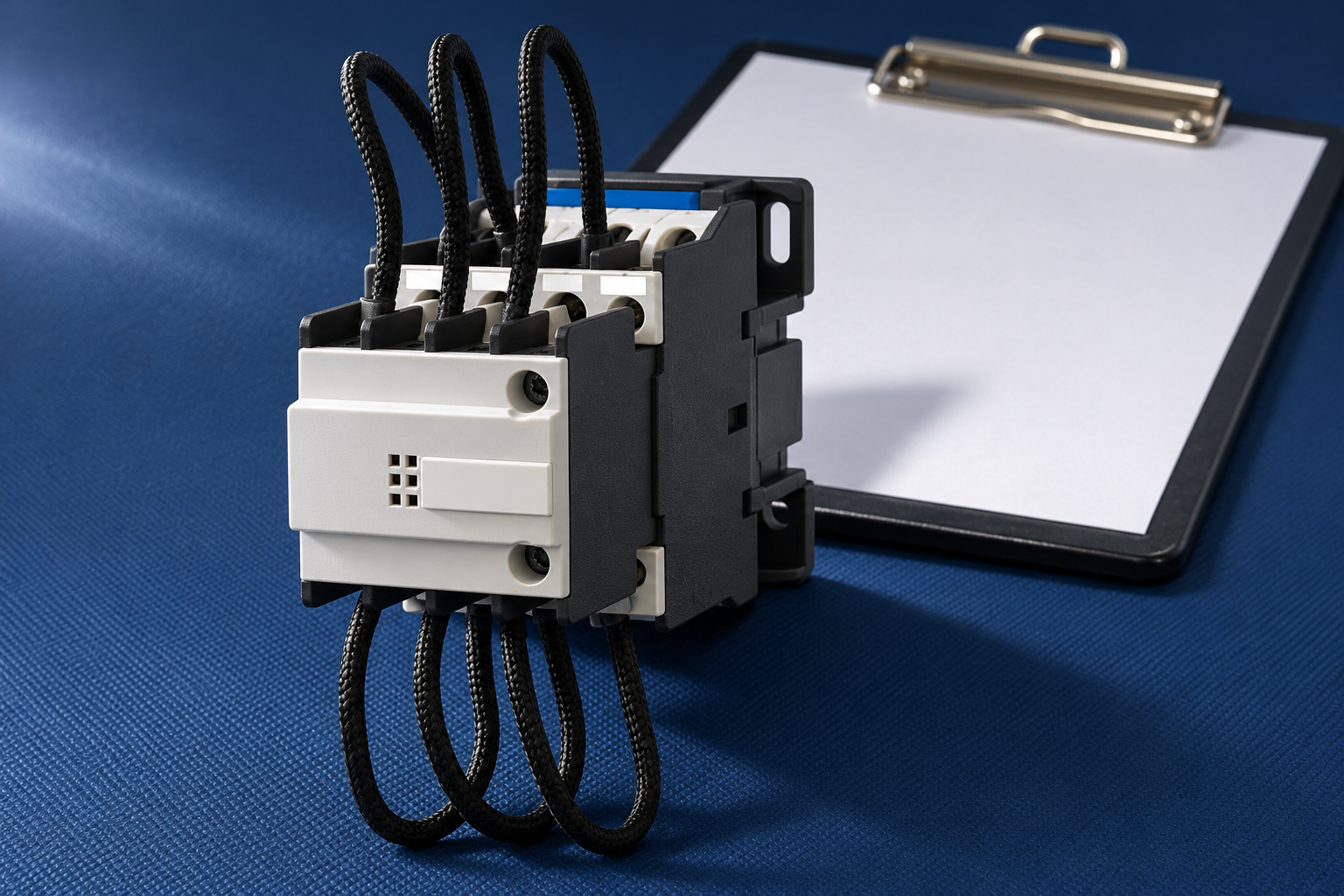
Preserve photographs before disturbing the assembly. Record the condition of the resistor leads and early-make contact assembly separately from the main terminals. Where damage prevents a reliable assessment, replacement may be the appropriate outcome, but the replacement should not be exposed to the same unresolved supply condition. Follow the supplier’s requirements on replacing an entire assembly versus individual approved parts.
Specify replacement parts with the complete duty
A replacement request should include capacitor stage duty, system voltage and frequency, the installed coil rating, auxiliary contact arrangement, mounting requirements, environmental conditions, and the approved switching sequence. Include the source of the capacitor’s actual operating current and the presence of detuning reactors. Do not select a replacement from a motor-current rating alone. The คู่มือการเลือกคอนแทคเตอร์สำหรับงานคาปาซิเตอร์ addresses that broader selection task.
Provide the supplier with the failed unit’s identification, event captures, command history, control schematic revision, and photographs of the damaged parts. Identify whether the proposed replacement changes pickup demand or control-output loading. A mechanically compatible unit may still require a control-circuit review. Obtain written confirmation of any differences before altering the approved panel arrangement.
Verify the repair under the conditions that exposed it
Create an acceptance plan before returning the stage to automatic operation. It should identify the approved coil supply limits, the intended command sequence, permitted test conditions, and the person responsible for release. Verify safe isolation and restoration controls first. Under the authorized commissioning procedure, confirm stable pickup and holding behavior without abnormal repetitive movement, then confirm correct stage response in the complete panel.
Include realistic supply conditions where they are within the approved test scope: simultaneous control loads, normal restoration sequences, and the operating state that originally accompanied the symptom. Do not manufacture an undervoltage event outside the equipment’s permitted operation. Record any condition that could not be reproduced. One successful unloaded operation should not be reported as proof that every intermittent cause has been eliminated.
Retain before-and-after event records, the repaired connection or replaced component identification, updated drawings where applicable, and the final release decision. If abnormal movement recurs, remove the affected stage from service under the approved procedure and reopen the diagnosis. The general automatic capacitor bank operating guide explains how the stage fits into the panel’s overall control and protection functions.
Educational background: how a contactor operates
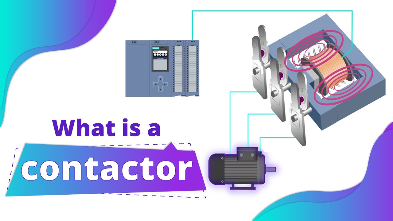
RealPars’ introductory lesson explains the relationship between a coil and mechanically operated contacts. It is background education from an automation training publisher, not a capacitor-duty design specification or an instruction to reproduce a live wiring demonstration. The companion contactor explanation supports this basic operating principle; installed equipment instructions govern the actual coil rating and permitted work.
คำถามที่มักถูกถาม
เสียงฮัมที่ดังสม่ำเสมอหมายความว่าแรงดันไฟฟ้าที่คอยล์ต่ำเกินไปหรือไม่?
Not necessarily. Distinguish a steady sound from repeated mechanical movement, then compare the actual coil supply with the installed unit’s specifications. Mounting, contamination, mechanical condition, and supply characteristics can also affect noise. Sound alone does not identify the failed component.
ค่าที่อ่านได้ตามปกติจากมิเตอร์สามารถยืนยันได้หรือไม่ว่าไม่มีปัญหาแรงดันไฟฟ้าต่ำกว่าปกติ?
ไม่ใช่ ค่าที่วัดได้หลังจากอุปกรณ์ดึงเข้าทำงานแล้วอาจไม่สามารถตรวจจับแรงดันไฟฟ้าที่ลดลงในช่วงเวลาสั้น ๆ ได้ ควรบันทึกเวลาและความสามารถในการบันทึกข้อมูลของเครื่องมือวัด และเปรียบเทียบแหล่งจ่ายไฟของคอยล์กับแหล่งจ่ายไฟต้นทางในช่วงที่เกิดเหตุการณ์ โดยใช้ขั้นตอนการวินิจฉัยที่ได้รับอนุมัติของสถานที่ปฏิบัติงาน.
ควรเพิ่มเวลาหน่วงของตัวควบคุมเพื่อหยุดอาการหน้าสัมผัสสั่นกระพือหรือไม่?
ทำได้เฉพาะในกรณีที่การตรวจสอบยืนยันว่าปัญหาเกิดจากลำดับการทำงานของระบบควบคุม และการปรับตั้งค่าใหม่ได้รับการอนุมัติแล้วเท่านั้น การปรับระยะเวลาหน่วงไม่ได้ช่วยแก้ไขปัญหาแหล่งจ่ายไฟของระบบควบคุมที่มีกำลังไม่เพียงพอ จุดเชื่อมต่อที่ไม่ดี คอยล์ที่ไม่ตรงตามข้อกำหนด หรือกลไกที่ถูกกีดขวาง ควรแยกแยะระหว่างการสลับทำงานไปมาระหว่างขั้นตอนต่าง ๆ ตามลำดับที่กำหนด กับความไม่เสถียรที่เกิดขึ้นระหว่างการสั่งงานอย่างต่อเนื่อง.
สามารถเปลี่ยนชุดตัวต้านทานที่ไหม้เสียหายเพียงอย่างเดียวได้หรือไม่?
That depends on the exact contactor's approved service instructions and the extent of damage. Assess the complete switching assembly and resolve the initiating fault before return to service. Do not bypass the current-limiting assembly or assume that replacing one visible part restores the original switching duty.