Kondansatör Bankaları için Dalga Üzerinde Nokta Anahtarlama
Kondansatör grupları için dalga üstünde anahtarlama AC bara gerilimi kondansatör uçlarındaki gerilimle eşleştiğinde her bir kondansatör kademesini kapatır; böylece ani gerilim farkı ve aşırı akım pik değeri küçük kalır. Otomatik güç faktörü panoları, rastgele kontaktör kapanışının genellikle yarattığı sigorta attırma, kontak aşınması ve bara dalgalanmaları olmaksızın kademelerin devreye girebilmesi için bu senkronize zamanlamayı kullanır.
Bu kılavuz, kalkış akımı mekanizmasını açıklar, sıfır gerilim anahtarlama kondansatörleri bir kondansatör grubu deşarj edildiğinde, anahtarlama kapatıldıktan sonra kalan kondansatör voltajı durumunda kullanın, arka arkaya anahtarlama tek otobüsteki tehlikeler ve kontaktörlerin karma anahtarlar ve entegre akıllı modüllerle nasıl karşılaştırıldığı senkronize anahtarlamalı kondansatör grubu kabinesi. Bir bankanın ne olduğu ve tesis reaktif güç kompanzasyonuna nasıl uyduğu hakkında bilgi almak için, şu konudaki ayrı makalemizle başlayın: Kondansatör bankaları; bu sayfa bu tanımı veya herhangi bir güç faktörü hesaplama adımını tekrarlamaz.
Kondansatör Bankaları İçin Dalga Üzerinde Nokta Anahtarlamasının Anlamı
Dalga üstü anahtarlama — genellikle senkronize anahtarlama veya kontrollü anahtarlama olarak adlandırılır — kontrol cihazının, açılan kontaklar arasındaki voltajın mümkün olan en düşük seviyede olması için anahtarı AC dalga biçimi üzerinde hesaplanan bir anlık zamanda kapatması anlamına gelir.
Kondansatörler ani voltaj değişimine karşı direnç gösterir. Baradaki anlık voltaj zaten yüksekken kondansatör terminalleri hâlâ sıfıra yakınsa, kapanma olayı neredeyse tam voltaj farkını tek seferde uygular. Dalga Üzerinde Kontrol (PoW) mantığı canlı dalgayı ölçer, mekanik veya hibrit anahtar kapanmayı gerçekten bitirdiğinde voltajın nerede olacağını tahmin eder ve hedef açıya denk gelmesi için komutu yeterince erken tetikler.
Tamamen deşarj olmuş bir batarya grubunda olağan hedef sıfır voltajda kapatmadır. Birkaç an önce devre dışı bırakılmış bir batarya grubunda ise hedef, deşarj dirençleri yoluyla yük azalırken veya kontrolör artık durumu takip ederken tepe voltajı veya ara bir seviye olabilir.
Elektrik iletim mühendisleri aynı fikri, özel kontrollü anahtarlama cihazlarıyla yüksek gerilim kesicilerinde uygular. Alçak gerilim otomatik güç faktörü panoları bunu bileşik anahtarlar, tristör destekli röleler veya entegre akıllı kondansatör modülleri aracılığıyla uygular. Donanım boyutu farklı olsa bile fizik kuralı ortaktır.
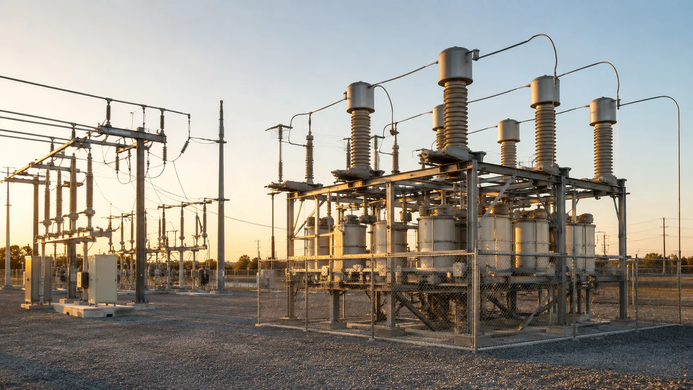
Kondansatör Bankası Anahtarlamasının Kontrolsüz Şekilde Aşırı Akım (Inrush) Oluşturma Nedeni
Kondansatör grubu kalkış akımı, terminal voltajının kondansatörün ayak uydurabileceğinden daha hızlı değişmeye zorlandığı her an şarj akımının akması zorunlu olduğu için ortaya çıkar.
AC terimleriyle ilişki bilindiktir: akım, gerilimin kapasitans üzerindeki değişim hızıyla orantılıdır. Bu nedenle rastgele bir kontaktör kapanışı, kontakların değdiği an sinüs dalgasının nerede olduğuna bağlı olarak aynı kvar adımı için geniş bir tepe akımları dağılımı üretebilir.
Çeşitli bitki faktörleri bu aralığı genişletmektedir:
- Sistem empedansı — düşük kaynak empedansına sahip rijit bir bara, daha büyük geçici tepe akımlarına izin verir.
- Anahtarlama öncesi şarj yakın zamanda açık devre olmuş bir durumdan ötürü hâlâ voltaj tutan bir kondansatör, deşarj olmuş bir birimden farklı bir ΔV görür.
- Paralel yollar — aynı veri yolundaki bir başka enerjilenmiş grup (veya banka), efektif LC şebekesini değiştirir.
Kontrolsüz anahtarlama, nadiren açılan tek ve küçük sabit bir adımda her zaman felaketle sonuçlanmaz. Değişen bir motor yükünü takip eden bir kontrolcünün saatte birkaç adım ekleyip çıkarabileceği otomatik panolarda bu durum sıkıntı yaratır.
İpucu: Mevcut sıfırda bir kademenin açılması, kondansatörleri şarjlı bırakır. Bu sıkışmış şarjı takip etmeden çok hızlı bir şekilde tekrar kapatmaya çalışan bir kontrolör artık kondansatör gerilimi pazarlama metinlerinde sıfır geçişten (zero-cross) bahsedilse bile hâlâ “rastgele” anahtarlama yapıyor. — kaynak: kapasitif yükler için şebeke kontrollü anahtarlama kılavuzları (artık yük hedefleri üzerine araştırma alıntısı)
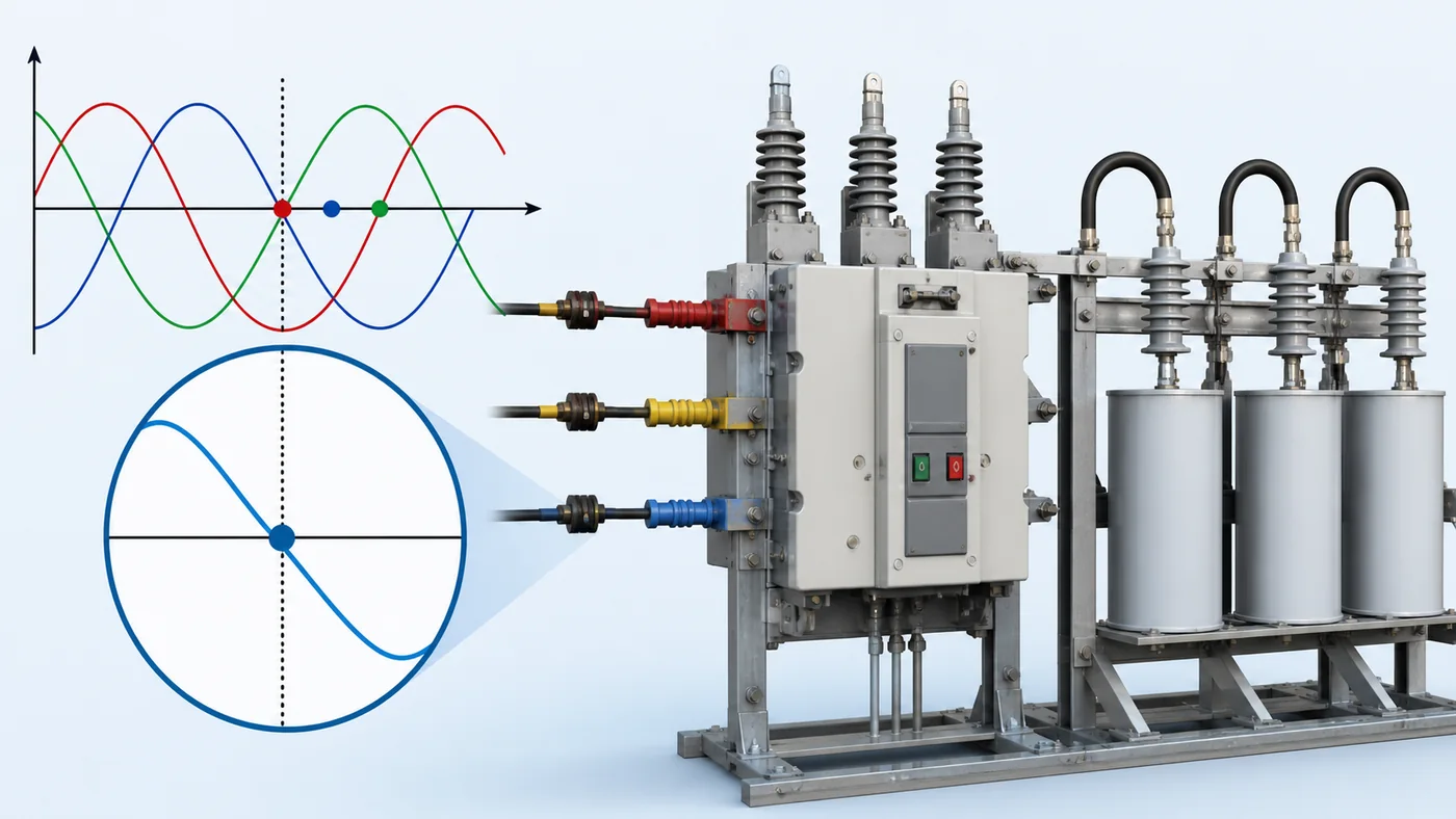
Sıfır Voltajda Kapama ve Şalter Kapalı Durumdayken Kalan Yük
Kondansatörler için sıfır voltajlı anahtarlama, kondansatör grubunun tamamen deşarj olduğu ve kontrolcünün sistem voltajı sıfır geçişine çok yakın veya tam o an bir kapama hedeflediği özel bir durumdur.
O anda hem bus hem de kondansatör terminalleri sıfıra yakın bir konumdadır, böylece ilk akım bir basamak olarak değil, sinüs dalgası doğal olarak yükseldikçe oluşur. Bu, çoğu AG kompozit şalterinin ve akıllı kondansatör modülünün tanıttığı ideal durumdur.
Gerçeklik, satın alma okullarının beklemesi gereken iki zorluk ekler:
- Mekanik ve hibrit gecikme — kapatma komutu, anahtarın çalışma süresi kadar hedefi öncelemelidir. Denetleyiciler bu nedenle dalgayı sürekli olarak ölçer ve saçılmayı telafi eder.
- Devre açıldıktan sonra kalan kondansatör gerilimi — akım sıfıra gittiğinde kapasitörler, deşarj dirençleri veya zamanla sönümlenme bunu azaltana kadar hat tepesine yakın bir voltajda şarjlı kalır. Şarj kalmış durumdayken yeniden kapatma, hedef açının artık sıfır voltajlı bir kapatma olmadığı anlamına gelir. Gelişmiş Dalga Üzerinde Nokta (PoW) sistemleri, kapasitif yükler için şebeke kontrollü anahtarlama kılavuzlarında açıklandığı gibi, bankanın deşarj olup olmadığını, tam şarjlı mı yoksa ikisi arasında bir yerde mi olduğunu takip eder.
| Kapatma istendiğindeki kondansatör şarj durumu | Tipik PoW yakın hedefi | Okuyucu çıkarımı |
|---|---|---|
| Tamamen deşarj olmuş | Gerilim sıfır geçişi | İlk ΔV'yi en aza indirir |
| Tamamen dolu (yeni açıldı) | Gerilim pik noktası | Hapsedilen yükle eşleşir |
| Partially discharged | Intermediate angle on the wave | Controller must track decay, not assume zero volts |
Without that state awareness, a cabinet may still slam steps at the wrong angle while the HMI label says “zero-cross.”
Aynı Bara Üzerinden Ardı Ardına Enerji Verme
Back-to-back switching and back-to-back energization both describe closing a capacitor step while another bank or step is already connected on the same bus. The second closure can produce very high inrush even when each step’s nameplate kvar looks modest.
The already-energized capacitors present a low-impedance path. The incoming step sees a stiff voltage source combined with the first bank’s stored energy, which can drive transient currents far above steady-state reactive current. Educational overviews of capacitor switching describe inrush frequencies from hundreds of hertz to a few kilohertz in severe same-bus cases.
Plant scenarios where this shows up:
- A controller adds step 3 while step 2 is still online instead of swapping steps.
- Two independent automatic cabinets share one compensation bus without interlocking.
- Rapid cycling after a brief outage when multiple stages try to return together.
PoW on each individual step helps but does not replace coordination logic. Minimum time between operations, interlocks, and controller algorithms that avoid overlapping closes still matter. CNBYG’s published BYFK composite-switch specification table, for example, lists minimum intervals between turn-on/turn-off and between consecutive connections—parameters buyers should align with controller programming, not ignore.
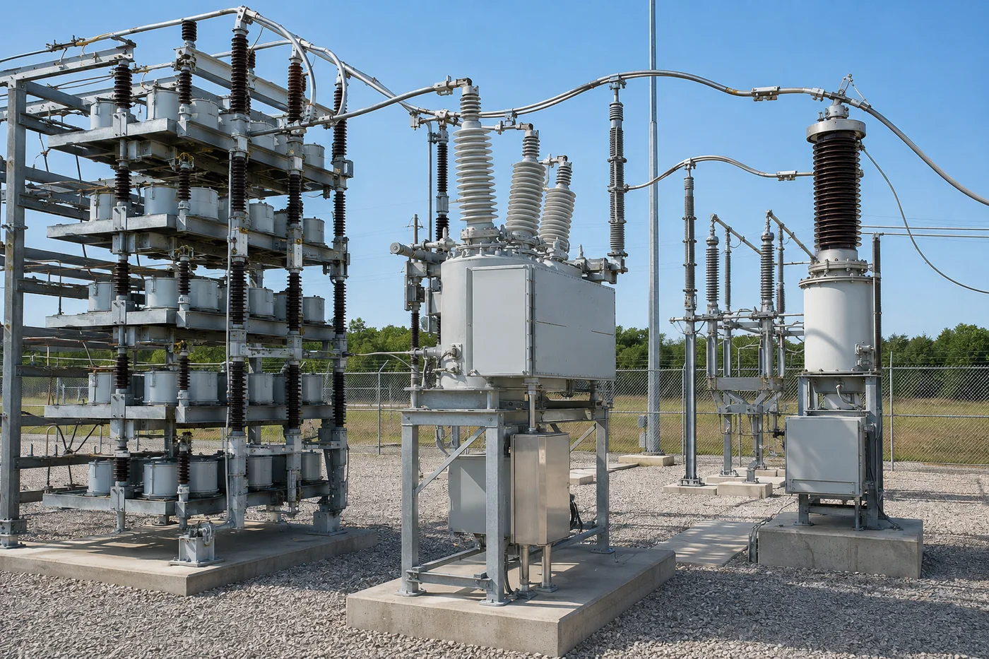
Kontaktör, Kompaund Anahtar ve Kesici Tabanlı Dalga Üzerinde Nokta Kontrolü
Three hardware classes cover most conversations—from LV cabinets to utility substations.
| Approach | How PoW is implemented | Standart kalıp | Dikkat et |
|---|---|---|---|
| Capacitor switching contactor (e.g., dedicated CJ19/GJ19 class) | Often basic timing; may rely on controller pre-contact or auxiliary logic | Cost-sensitive fixed steps with infrequent switching | Random-angle closes still possible if controller does not synchronize |
| Compound / composite switch (semiconductor + magnetic hold relay) | Microprocessor selects turn-on at voltage zero and turn-off at current zero | LV automatic PF cabinets with frequent stepping | Still needs correct residual-voltage logic and minimum intervals |
| HV breaker + controlled switching device (CSD) | Breaker with high repeatability; rate of decrease of dielectric strength (RDDS) and pole-scatter budgets per IEEE application guides | Utility and large MV banks | Not a direct substitute for LV compound-switch specs |
High-voltage application notes stress breaker repeatability on the order of ±0.5 to ±1.0 ms and sufficient rate of decrease of dielectric strength (RDDS) when zero-cross is the target. Those numbers belong to breaker selection on transmission systems, but they explain why “any contactor with a zero-cross label” is not interchangeable with a compound switch engineered for capacitive duty.
At low voltage, the reactive power compensator hub groups controllers, switches, and capacitor steps that are specified together. Switching hardware should be chosen with the controller’s PoW algorithm, not as an orphan part number.
Alçak Gerilim Tesis Pano Kabinlerinde Nokta-Dalga Anahtarlama Ne Zaman Kazanç Sağlar?
Point-on-wave switching pays off most when capacitor steps switch often and when inrush would otherwise limit how aggressively the controller can follow load.
Strong fits:
- Multi-step automatic PF cabinets on motor-heavy plants where lagging reactive demand swings across shifts.
- Steps large enough to disturb the bus when closed at a bad angle—nuisance fuse operations, contact pitting, or voltage flicker on sensitive loads.
- Projects where the utility or internal power-quality spec limits switching transients even if steady-state power factor already looks acceptable.
Weaker fits:
- A single fixed capacitor step that rarely disconnects—PoW hardware adds cost with little operational benefit.
- Plants where harmonic distortion, not switching angle, is the primary failure mode—see the limit below.
Published extra-high-voltage studies comparing uncontrolled energization with point-on-wave zero-cross control report large reductions in peak transient current and voltage in their test and simulation cases. Those figures illustrate the mechanism; they are not LV nameplate guarantees for your site.
Automatic stepped banks also multiply exposure: each energization is another transient event. Educational material on shunt capacitor applications notes that switching overvoltages and inrush accompany automatic banks even when steady-state power factor improves.
Önemli: Point-on-wave switching limits energization stress; it does not detune a bank against harmonic resonance. Field discussions of automatic PF stages describe humming reactors, overheated capacitors, and blown fuses when plain capacitors interact with nonlinear loads—symptoms that PoW alone will not cure. Detuned reactors, harmonic analysis, or active solutions may still be required on distorted buses. — source: IPQDF harmonikleri ve güç faktörü kondansatörleri
Kondansatör Bankası Kademeleri İçin Anahtarlama Donanımı ve BYFK Ürün Uyumu Seçimi
When you specify hardware for a new or retrofitted cabinet, match the switch class to how often stages move and how much inrush your bus can tolerate.
Conventional capacitor contactors such as the GJ19 series switching capacitor contactor remain appropriate where steps are few, switching is slow, and the controller’s strategy is conservative. They are the baseline comparison in many bids—not the end of the story for aggressive automatic controllers.
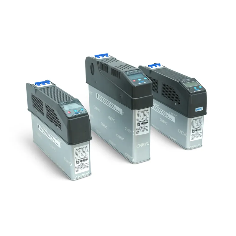
Compound switches such as the BYFK series intelligent low-voltage composite switch target capacitive duty with voltage zero-crossing conduction and current zero-cross cutoff. CNBYG’s published specification table for BYFK lists inrush below 1.5 times rated current, response time under one second, minimum five-second spacing between turn-on and turn-off, and thirty-five seconds between consecutive connections—values that should be checked against your controller’s staging profile.
Integrated intelligent capacitors such as the BY81 serisi akıllı kondansatörler embed measurement, control, and synchronous zero-crossing switching inside the module when a distributed step-by-step architecture fits better than a central contactor bank.
Whichever path you take, confirm three items with the supplier and your panel builder:
- Controller and switch share one PoW algorithm including residual-voltage handling.
- Minimum intervals and interlocks prevent back-to-back overlaps your bus cannot absorb.
- Harmonic study precedes energization on VFD-heavy plants—PoW is not a substitute for detuning.
SSS
What is point on wave switching for capacitor banks?
It is controlled closing (and sometimes opening) synchronized to a target angle on the AC voltage wave so the voltage difference across the switch at contact make is minimized, which limits inrush when the step connects.
Why does switching a capacitor bank cause inrush current?
Capacitors require current whenever terminal voltage changes quickly. Closing at a high instantaneous ΔV forces a large charging current until the capacitor matches the bus.
Is zero voltage switching the same as point on wave?
Zero-voltage switching is the discharged-bank case of point-on-wave control—closing at or near zero volts. PoW also covers closes at peak or intermediate angles when residual charge remains after a previous open.
What is back-to-back capacitor bank switching?
It is energizing a second bank or step while another is already connected on the same bus. The combined network can produce much higher transient current than either step alone.
Does switching off discharge the capacitors immediately?
No. When current is interrupted at zero, capacitors typically retain near-line voltage until discharge resistors or time decay reduces it. The next close must account for that trapped charge.
Do I still need detuning if I use point on wave switching?
Often yes on plants with significant harmonics. PoW reduces energization transients; it does not move resonance points away from characteristic harmonics the way a detuned reactor bank does.
Can low-voltage plants use point on wave switching?
Yes. LV automatic PF cabinets commonly use compound switches or integrated intelligent capacitors with zero-cross control rather than utility-scale breaker CSDs.
How is a compound switch different from a capacitor contactor?
A compound switch uses intelligent timing plus hybrid switching elements to target voltage zero-cross turn-on and current zero-cross turn-off for capacitive duty. A conventional contactor may rely on simpler mechanics unless paired with a controller that truly synchronizes every close.
Kaynakça
- IEEE Technology Navigator — Capacitor Banks and controlled switching
- E3S Web of Conferences — Diminution of Transient Disturbances for High Voltage Application Integration
- IEEE SA — IEEE C37.012-2022 Guide for Application of Capacitive Current Switching
- Elektrik Teknolojisi — Kondansatör Bankalarının Özellikleri ve Uygulamaları
- IPQDF — Harmonics and Power Factor Capacitors: Understanding Failure, Resonance, and the Filter Solution