


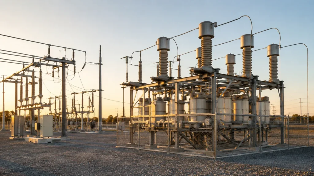
Why do we use a capacitor bank in a substation? The short answer is simple: a shunt capacitor bank injects reactive power (vars) locally on a bus or feeder so voltage can be supported under load, reactive current does not travel as far through transformers and lines, and power factor improves for industrial loads served from that area.
The four main reasons are to support bus voltage, improve power factor, reduce reactive current and I²R losses upstream, and release usable capacity in transformers and feeders. A bank does not create real power, and it is not a universal cure for undervoltage; its size, location, step control, protection, and harmonic interaction must be checked for the actual network.
This article explains that substation role—voltage support, reactive compensation, and load-flow effects—then maps typical bus and feeder placement, contrasts utility-scale banks with plant low-voltage correction, and notes switching and harmonic boundaries. For what a bank is as equipment, start with Kondansatör bankaları; for kvar math, use the live güç faktörü düzeltmesi için kondansatör bankası boyutlandırması guide instead of treating this page as a calculator.
What Substation Shunt Banks Do on the Bus
A substation shunt capacitor bank sits in parallel with an energized bus or feeder and supplies leading reactive current that offsets lagging demand from transformers, motors, and other inductive equipment downstream.
Utilities and large industrial customers do not install that hardware for decoration. The bank is a static var source—no rotating machine—meant to change how reactive power moves through the substation and what the voltage profile looks like at critical nodes.
On the same bus you may also see breakers, instrument transformers, and sometimes other reactive devices, but the capacitor bank’s core job is local Q injection. That Q supports power factor for commercial and industrial loads tied to the substation and reduces how much magnetizing current must be imported from farther upstream.
If the vocabulary still feels abstract, the linked definition article walks through bank construction and shunt connection before you dive into placement studies here.

Voltage Support When Feeders and Transformers Are Loaded
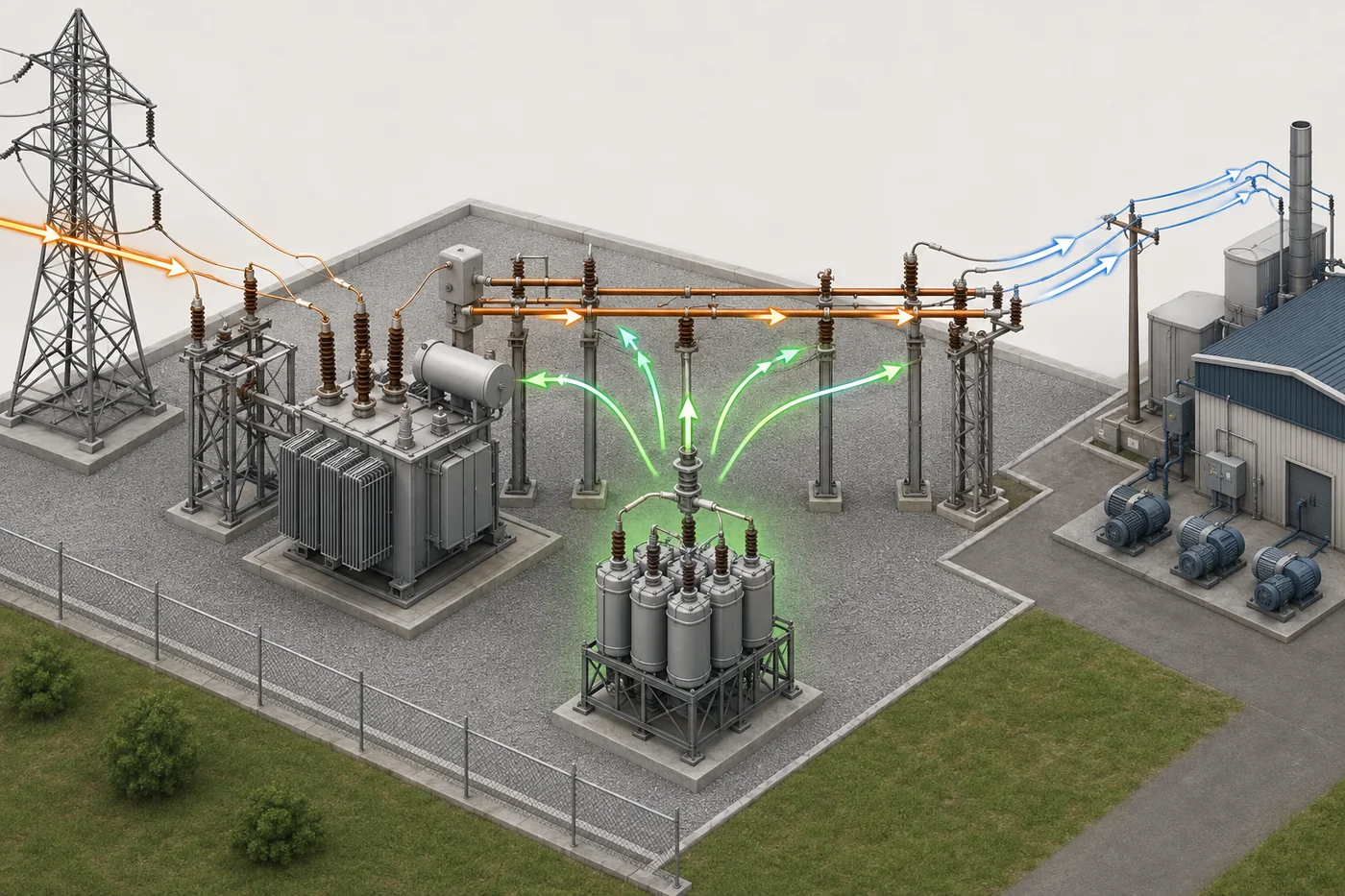
Shunt capacitor banks support substation voltage support goals because added reactive power tends to raise the bus voltage where the bank connects, especially when feeders are heavily loaded and the system is relatively weak.
In planning language, the voltage increase from injecting Q kilovolt-amperes reactive relates to the short-circuit strength at that bus—often discussed as an approximate Q/S effect. You do not need to run a full load-flow study to grasp the idea: when summer peak pushes voltage down on a long feeder, a switched bank step that adds vars locally can help keep end-of-line voltage inside the band the utility targets.
That is different from saying capacitors are a universal fix for every undervoltage. If the problem is primarily real-power deficit or a high-impedance fault path, vars alone will not solve it. Engineers still study load level, regulator taps, transformer LTC settings, and whether the right fix is generation, reconductoring, or reactive support.
For procurement readers, the practical takeaway is simple: substation banks are often specified when studies show voltage or reactive support at a bus is cheaper or faster than rebuilding miles of feeder—provided switching and harmonic risks are managed.
Reactive Compensation and Load-Flow Effects
Reactive compensation at a substation changes load flow because reactive power / vars sourced at the bank stop acting like a distant burden on upstream transformers and transmission elements.
Inductive loads draw lagging current. Without local compensation, that reactive component flows through the substation transformer, the high-side bus, and sometimes far into the transmission system. Each amp of reactive current still produces I²R loss and occupies thermal capacity even though it does not turn motors.
When a shunt bank supplies leading vars near the load pocket, the reactive loop shortens. The transformer sees a lower reactive component on its secondary side. Feeder current for the same real-power load can drop. Released MVA capacity on the transformer may allow additional customer load without a transformer change-out.
Power factor improvement is the familiar plant-side phrase for the same physics. At substation level the metric still matters because tariffs and interconnection studies often track displacement power factor for large customers. Many U.S. utilities may assess extra charges when site power factor sits below about 0.95, so a bank that keeps regional Q balanced can align with both voltage and billing goals—tariff details always belong to the serving utility, not a generic article.
Broader compensation concepts appear in Reaktif güç kompansazyonu if you want the vocabulary before a feeder study.
Bus, Feeder, and Transmission-Level Placement
Substation capacitor banks connect where the reactive problem and the voltage problem intersect—on a main bus, on individual distribution feeders, or at higher-voltage interfaces that feed the substation.
| Yerleştirme | Typical connection | Güç | Dikkat et |
|---|---|---|---|
| Main substation bus | Bank switched onto the primary distribution bus | One coordinated package; supports multiple outgoing feeders | A large step can move voltage on the whole bus; coordination with other banks matters |
| Distribution feeder | Bank at feeder head or mid-feeder switch point | Targets a long or heavily loaded feeder where end voltage sags | More banks to maintain; protection and switching per feeder |
| Transmission / sub-transmission interface | Higher-voltage static var support into the substation | Addresses regional reactive balance and voltage on the grid side | Utility-grade protection, switching, and studies; outside typical plant LV scope |
Engineers choose among these after load-flow and voltage studies, not from a slogan. A downtown network with dense commercial load may justify bus-mounted steps. A rural feeder with irrigation motors at the far end may justify a feeder-switched bank timed to those seasonal peaks.
Transmission-level shunt capacitor installations—part of static reactive compensation on EHV/HV networks—solve regional var balance problems plant readers rarely touch directly. The concept still matters: the same shunt-Q idea scales from a 480 V cabinet to a rack of cans on a 34.5 kV bus, but the voltage class, protection, and switching equipment do not.

Substation Banks vs Plant Low-Voltage Correction
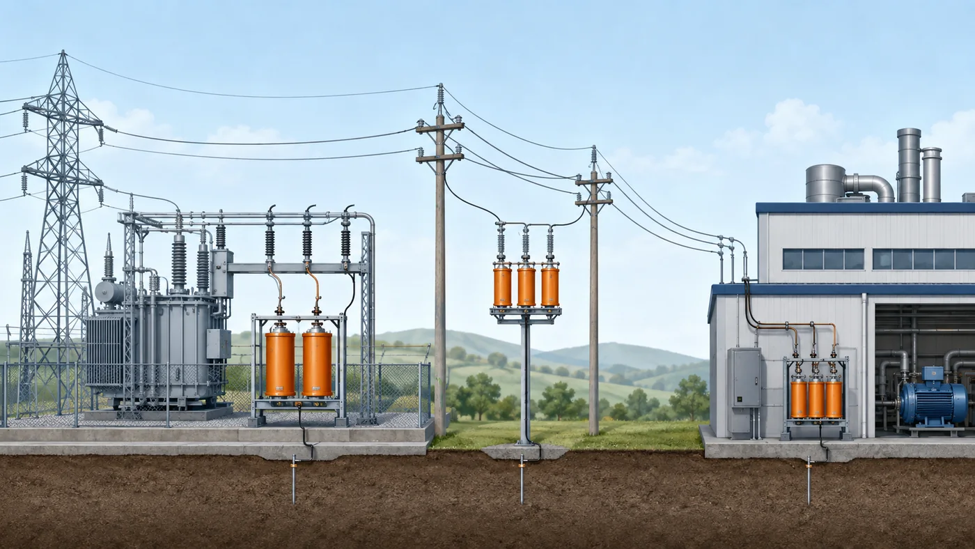
Substation capacitor banks and plant low-voltage correction solve related reactive-power problems at different voltage levels, with different packaging and protection expectations.
| Topic | Substation / utility-scale shunt bank | Plant LV automatic capacitor bank |
|---|---|---|
| Typical voltage class | Distribution and sub-transmission buses (kV class) | 208–600 V switchboards and MCCs |
| Physical form | Open-air racks, metal-enclosed MV assemblies, pole structures | Cabinet steps, contactor or semiconductor-switched modules |
| Who studies it | Utility planner or interconnection engineer | Plant engineer or electrical contractor |
| Protection focus | Bank unbalance, fuse coordination, inrush, utility relaying | Step sequencing, controller PF targets, local harmonic environment |
| CNBYG product fit | Conceptual background only—CNBYG supplies LV compensation hardware | BY81 intelligent capacitors, BSMJ shunt units, controllers, reactors |
A plant LV capacitor bank at the main low-voltage switchboard is still “centralized” in the language of power-factor correction, but it is not the same object as a utility rack on a 13.8 kV bus. The plant device corrects vars inside the facility fence. The substation bank changes what the utility sees at the point of common coupling and how voltage behaves for every customer on that feeder.
Readers who quote LV compensation cabinets should understand substation context so they do not confuse MV utility scope with a BY81 module spec. Readers who work with utilities should not assume a plant PFC cabinet replaces a feeder bank study.
Switching, Harmonics, and Design Boundaries
Substation capacitor banks demand switching discipline and harmonic awareness because energizing capacitors is never a zero-impact event and nonlinear loads can turn a helpful bank into a resonance problem.
Closing a bank onto an energized bus produces switching inrush current whose peak depends on system impedance and any pre-existing charge on the capacitors. Utilities mitigate that stress with controlled switching, pre-insertion resistors or reactors, and operating rules about how many steps may be on a bus at once. Back-to-back switching—energizing a second bank while another is already online on the same bus—can produce especially severe inrush and is a standard study item in shunt-capacitor application guides such as IEEE 1036.
Harmonics raise a parallel concern. Variable-frequency drives, rectifiers, and other nonlinear loads inject current at multiples of 60 Hz. Capacitive impedance falls with frequency, so harmonic current seeks the bank. If the bank and system inductance form harmonik rezonans near a characteristic harmonic, voltage distortion can climb, fuses can run hot, and capacitors can fail early.
Sahadan: Professional forum discussions describe automatic power-factor stages that produce loud humming, overheating reactors or capacitors, and blown fuses—sometimes severe enough that operators leave equipment off. That pattern is a warning about resonance and nonlinear loads, not an argument against all reactive compensation.
Önemli: Do not add substation or feeder capacitor steps on a harmonic-rich network without a study. Plain shunt banks are economical when the spectrum is mild; detuned reactors, filters, or alternate var technologies may be required when drives dominate. See the IPQDF harmonikleri ve güç faktörü kondansatörleri discussion for resonance symptoms and detuning concepts.
Recommended LV Compensation Hardware After Substation Planning
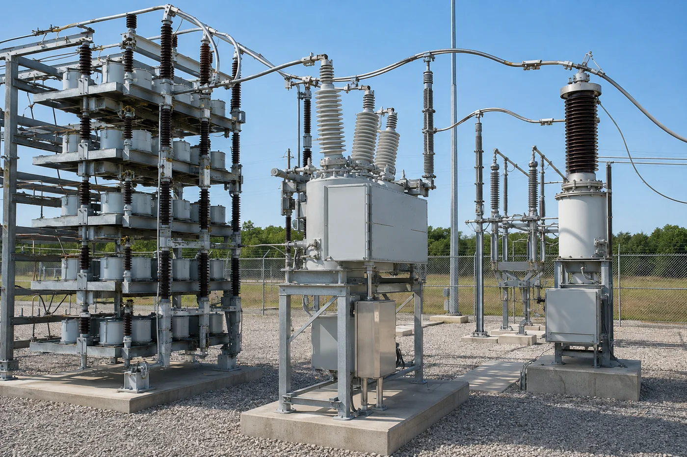
Once you understand why substations use shunt banks for voltage, Q, and load-flow relief, plant-side specifications usually move to low-voltage compensation cabinets—not to a utility MV rack quote from the same catalog line.
CNBYG reaktif güç kompanzasyon merkezi groups LV building blocks that mirror the plant half of the table above: shunt capacitor units, intelligent capacitor modules, series reactors for detuning, and controllers. The BY81 serisi akıllı kondansatörler are an intelligent capacitor (BY81) option that combines measurement and control with synchronous zero-crossing switching so steps can engage with less uncontrolled inrush than a naive contactor closure.
BSMJ kendi kendini iyileştiren şant kondansatör units remain the metallized-film cores inside many LV steps as a self-healing shunt capacitor (BSMJ) building block. Where harmonic measurements show risk, pair capacitors with a series reactor from the same compensator family rather than assuming a plain step is harmless.

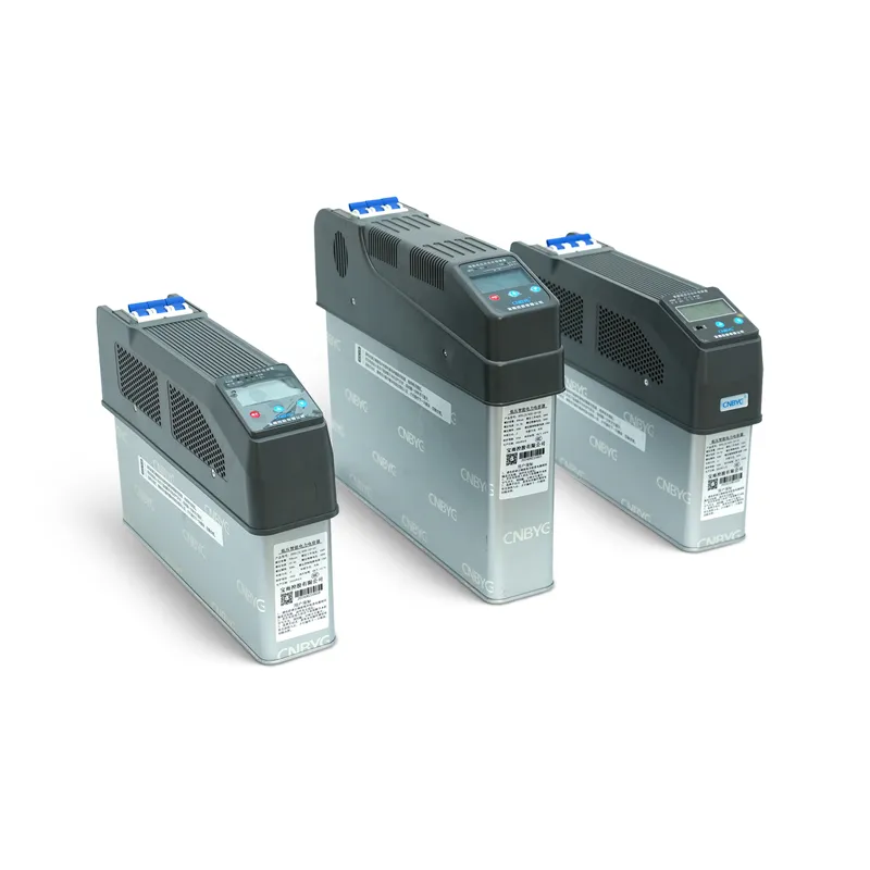
None of that hardware replaces a utility feeder-bank study, and none of it removes the need for kvar math on the plant side. Open the dedicated güç faktörü düzeltmesi için kondansatör bankası boyutlandırması worksheet when you move from substation context to plant totals. Use this page to keep substation why/where separate from plant what/how-much.
SSS
Trafo merkezinde kondansatör grubu neden kullanılır?
Bir trafo merkezi, yerel reaktif güç sağlamak için bir şönt kondansatör grubu kullanır; böylece yük altında bara gerilimi desteklenir, reaktif akım trafoları ve fiderleri aşırı yüklemez ve o bölgeden beslenen müşteriler için güç faktörü iyileşir.
Bir şönt bankası voltajı nasıl destekler?
Bir bara reaktif güç enjekte etmek, yerel gerilimi artırma eğilimindedir—yaklaşık olarak o düğümdeki kısa devre gücüne oranla eklenen Q ile orantılı olarak—bu nedenle aşırı yüklenmiş fiderler puant talep sırasında daha az gerilim düşüşü yaşar.
Bankalar nereye bağlanır — ana baraya mı yoksa besleyiciye mi?
Ana dağıtım barasında, bireysel besleyicilerde veya trafo merkezindeki daha yüksek gerilim arayüzlerinde bağlanabilirler. Seçim, ilgili şebeke için güç akışı ve gerilim analizlerini takip eder.
Bir trafo merkezi (substation) bankası ile bir santral AG (alçak gerilim) bankası arasındaki fark nedir?
Trafo merkezi bataryaları, elektrik dağıtım şirketinin koruma ve anahtarlama incelemelerine sahip, OG sınıfı raf tipi veya kapalı montajlardır. Tesis AG bataryaları ise tesis içinde yer alan, kontrolörler ve modüller içeren 208–600 V değerindeki pano kademeleridir; ilgili fizik aynı, ekipman sınıfı farklıdır.
Can substation banks cause harmonic problems?
Yes. Together with system inductance, a bank can form parallel resonance near a harmonic frequency, especially when VFDs and rectifiers dominate the load. Studies and detuning—or other var technologies—address that risk.
What is the difference between a capacitor bank and a synchronous condenser?
Both can supply vars, but a capacitor bank is static equipment with no rotating parts, while a synchronous condenser is a rotating machine that can also supply or absorb vars dynamically. Banks are usually lower cost for steady Q; condensers fit some dynamic or bi-directional var needs.
How do you size a capacitor bank?
Use measured real power and present versus target power-factor data—or an equivalent worksheet—on the dedicated kondansatör bankası boyutlandırma page. Substation studies use utility-grade load-flow tools beyond that plant worksheet.
When should I look at LV intelligent capacitors?
After you confirm plant-side compensation is the right scope, consider intelligent capacitor modules when you need integrated sensing and controlled zero-crossing switching in an LV cabinet. Compare BY81 and related options on the reaktif güç kompanzatorü hub before you lock a bill of materials.