SVG Maintenance and Inspection Checklist
SVG Maintenance and Inspection Checklist
An SVG maintenance and inspection checklist should protect the equipment, preserve the measurement chain and confirm that the unit still meets its intended power-quality objective. The checklist is more than a visual walk-around: it connects cabinet condition, airflow, electrical connections, CTs, firmware, alarms and measured performance. A short, repeatable record is more useful than an annual form that is completed without operating evidence.
Use the CNBYG SVG product page to identify the product family, then use the exact model manual for isolation, access, torque, filter and replacement requirements. Never open or service an energized enclosure outside the site’s approved electrical-safety program.
Maintenance records are also a useful design signal. Repeated fan alarms, rising temperature, unstable CT readings or a growing number of manual resets can indicate that the original installation assumptions no longer match the plant. Trend those findings across visits and escalate patterns before they become an outage.
Maintenance principles
Keep three boundaries clear. First is the physical boundary: enclosure, covers, seals, vents, filters, fans and cable entries. Second is the electrical boundary: terminals, protection, CTs, voltage sensing, phase sequence and insulation condition. Third is the performance boundary: voltage, current, kvar, power factor, harmonics, temperature, alarms and control response.
Inspect more frequently when the environment is dusty, hot, humid, corrosive or subject to vibration. A clean room does not remove the need for records; it only changes the likely failure modes. Use the alarm history and temperature trend to adjust the interval rather than relying on a calendar alone.
Core checklist
The following table separates what to look at from the evidence that closes the task.
| Area | Inspection question | Evidence or action |
|---|---|---|
| Safety and isolation | Are isolation points, barriers and permits correct? | Approved isolation record and absence-of-voltage test per site procedure. |
| Enclosure | Are covers, hinges, seals, vents and mounting secure? | Photographs, defect list and approved repair reference. |
| Airflow | Are fans, filters, clearances and room ventilation unobstructed? | Filter condition, fan status, ambient and temperature trend. |
| Power connections | Are terminals, lugs, cables and protective devices sound? | Visual/thermal evidence and torque work completed to the manual. |
| Measurement | Are CTs, voltage sensing and phase labels unchanged? | CT ratio, polarity, phase assignment and reference-boundary check. |
| Controls | Are settings, firmware, communications and priorities approved? | Settings export, firmware record and change-control reference. |
| Performance | Does the SVG respond at representative load states? | Voltage, current, kvar, PF, harmonics, alarms and synchronized trace. |
| Records | Can the next technician understand what changed? | Signed checklist, photos, parts, findings and next due date. |
Before opening the cabinet
Review the previous service record, active alarms, temperature trend and recent plant changes. Ask whether a new VFD, transformer, capacitor bank, generator or process cycle has changed the electrical environment. Confirm the current one-line and the SVG settings export are available before isolating the unit.
Make the work area safe, identify all energy sources and follow the site’s lockout/tagout and absence-of-voltage process. Allow specified discharge time. Do not remove covers or filters simply because the front display is dark. A dark display is not proof that every hazardous source is isolated.
Airflow and thermal inspection
Dust on a filter, a blocked vent or recirculating warm air can reduce available current before an overtemperature alarm appears. Check inlet and outlet paths, cabinet roof clearance, fan direction, filter frame, room ventilation and nearby heat sources. Compare the present ambient and enclosure temperature with the commissioning baseline.
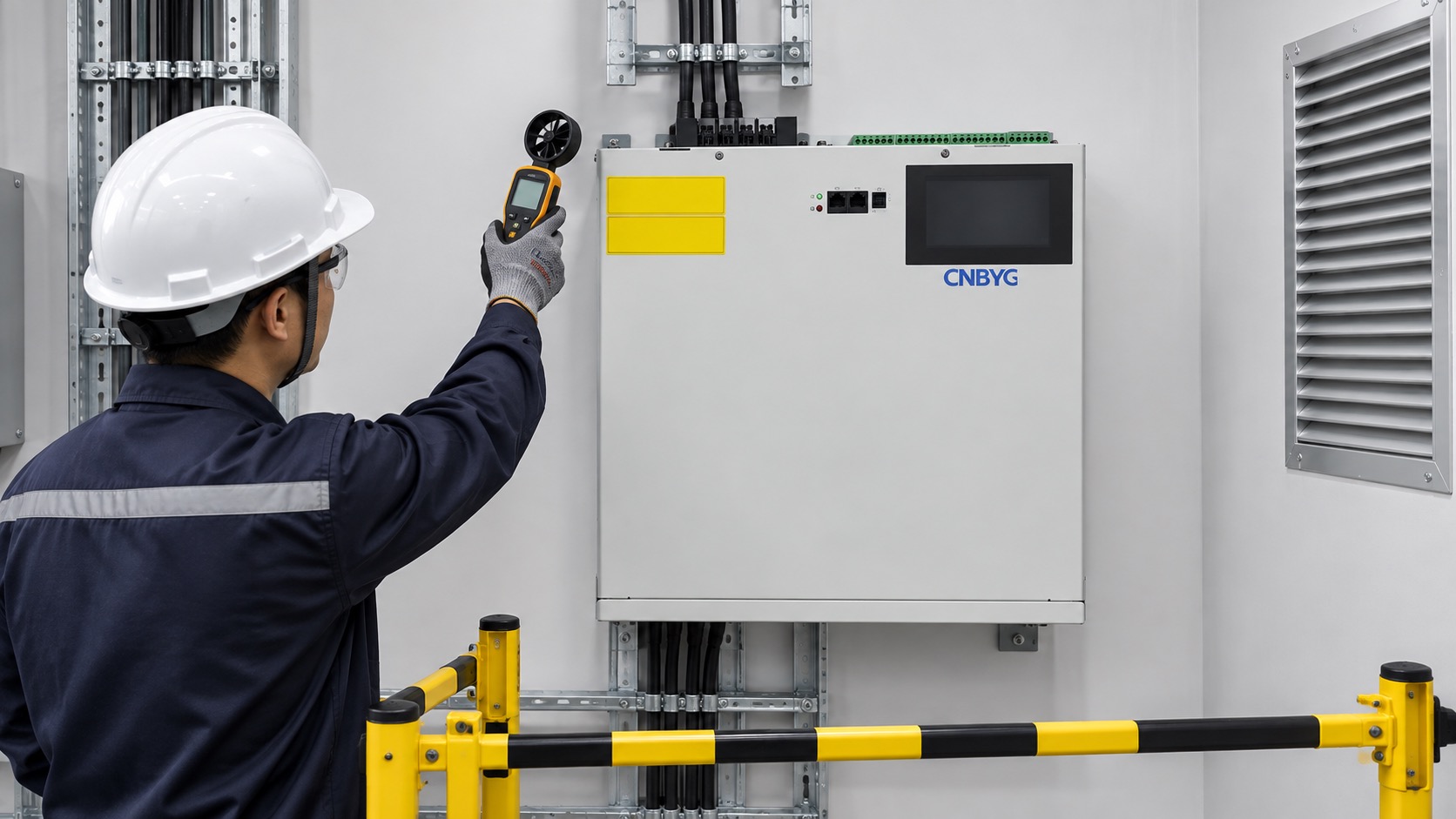
Use an approved instrument to compare accessible temperatures, but do not infer internal component temperature from one external point. If a thermal image is taken, save the measurement range, emissivity assumptions and operating state. Replace filters and fans only with approved parts, and verify that the change has not reduced ingress protection or altered cable sealing.
Electrical and measurement checks
Inspect terminals, lugs, bus connections, protective devices and cable supports for discoloration, looseness, contamination or mechanical strain. Any torque check must follow the model manual and the site’s approved method; do not apply a generic torque value to an unknown terminal.
Reconfirm CT ratio, polarity, phase assignment, shorting arrangement and location after any wiring work. Compare the SVG’s voltage reference with an independent analyzer. A maintenance visit can accidentally introduce a phase-label or CT error that looks like a control failure. Record the reference point used for power factor and kvar.
If the unit operates in a parallel bank, identify each module and compare current, temperature, fan status and alarm history. Uneven sharing is a finding even when the combined output appears acceptable. Escalate repeated imbalance instead of compensating by changing a gain without an approved study.
Controls, firmware and communications
Export settings before making changes. Record firmware version, communication address, compensation priority, target, limits, delay, alarm thresholds and any generator or capacitor-bank interlock. Compare the export with the approved baseline and explain every difference.
Test communications without changing control ownership. A monitoring link may be read-only, while a plant controller may be authorized to write a setpoint. Make that distinction explicit. After a firmware update, repeat the relevant functional and alarm checks; do not treat a successful boot as proof that the previous behavior is preserved.
Functional performance check
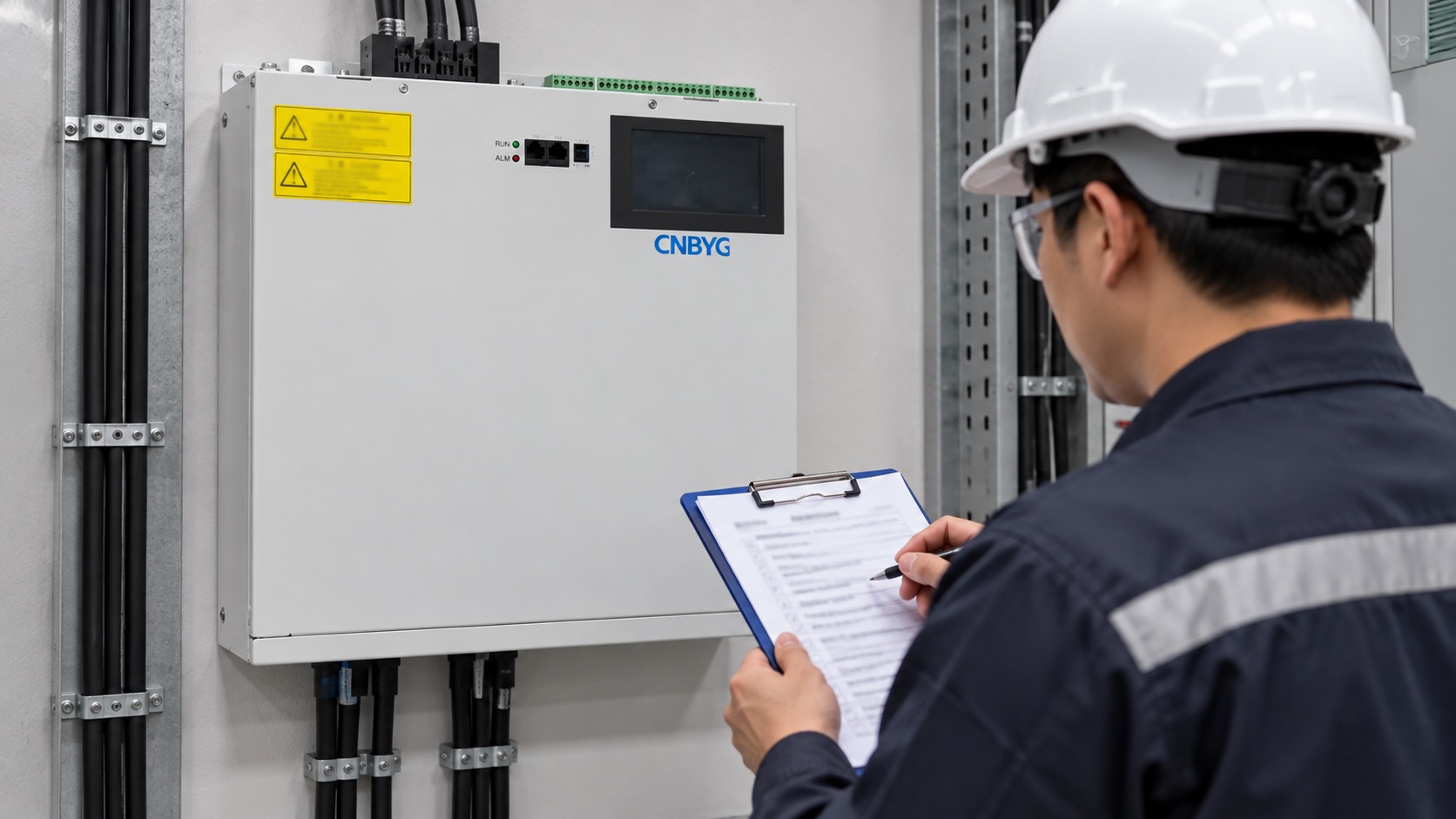
Choose representative operating states: light load, normal production, the highest expected reactive demand and any generator or capacitor-bank transition that is permitted by the operating procedure. Record voltage, current, kW, kvar, power factor, harmonic current, temperature, fan state and alarms at synchronized timestamps.
Compare the result with the commissioning baseline and the current target, not with an unrelated day. A changed production recipe or voltage can explain a different output. If the SVG is at its current limit, record the limit rather than adjusting the target to make the display look better. The SVG power-factor troubleshooting guide gives a structured approach when the target is not reached.
Maintenance intervals and escalation
Use condition-based triggers in addition to calendar intervals. Shorten the interval after a high-temperature event, repeated fan alarm, filter blockage, abnormal noise, communication dropout, water ingress or a process change. A repeat alarm after two documented corrective attempts should trigger a qualified design or supplier review.
Set a clear owner for each interval. Operations can record daily status and alarms; a qualified electrical technician can perform isolation, torque checks and measurement verification; the system owner approves changes to targets, priorities and firmware. This division prevents a routine visual check from being mistaken for an electrical performance test. Keep the next due date visible in the asset register and carry open defects into the next shift handover. If a temporary bypass or limited mode is necessary, record its expiry and the condition that releases it. Maintenance is complete only when the equipment is returned to an approved state or the outstanding risk is formally accepted.
Use the SVG output-capacity and voltage guide when a maintenance trend shows that current limiting occurs during voltage variation. The operating record should distinguish a maintenance defect from a normal voltage-dependent capacity limit.
Keep spare fans, filters, control boards and fuses only when the model and revision are confirmed. Label removed parts and record serial or revision information. Do not mix an unapproved replacement into a parallel bank and assume the controller will compensate automatically.
After any part replacement, confirm the fasteners, covers, cable glands and protective barriers are restored before energizing. Note the replacement serial number and the reason for the change. A small hardware change can alter airflow, sensor placement or communication behavior, so the follow-up test should cover the affected function as well as the original alarm.
The SVG commissioning checklist is useful when a maintenance intervention changes wiring, firmware, CTs or protection. Treat that work as a controlled change and repeat the affected acceptance cases.
Handover record
The completed record should contain the asset ID, date, technician, isolation reference, operating state, measurements, photos, alarms, findings, parts, settings export, firmware, corrective action, limitations and next due date. State clearly whether the unit was returned to automatic compensation, left in a limited mode or kept isolated.
Store raw analyzer files with the signed summary. A screenshot can show a number but cannot prove the measurement boundary, duration or operating state. The next technician should be able to reproduce the check without relying on verbal history.
Frequently asked questions
How often should an SVG be inspected?
Use the model manual and site risk assessment as the baseline, then adjust for dust, heat, humidity, vibration, alarms and load changes. Condition-based triggers often justify an earlier inspection.
Can I clean the filter while the SVG is running?
Only if the approved model procedure explicitly allows it and the site’s safety rules are met. Many inspections require isolation; a dark display alone is not isolation.
Do maintenance checks require a power-quality analyzer?
A visual check may not, but a performance or troubleshooting check should use a suitable instrument to compare voltage, current, kvar, PF and harmonics at the defined boundary.
What is the most important record after a repair?
Save the original event, the corrective action, the replacement part or setting change and a repeat measurement under the same representative operating condition.
Conclusion
An SVG maintenance checklist is successful when it links safe isolation, physical condition, airflow, electrical measurement, controls and repeatable performance evidence. Keep the checklist short enough to use, specific enough to audit and tied to the exact model. That discipline protects uptime and makes later power-quality decisions based on evidence rather than assumptions.
Neutral video: electronics maintenance background
The NPTEL lecture below provides general educational context for electronics cooling. It is not a model-specific SVG maintenance instruction.