Open-Loop vs Closed-Loop AHF Control
Open loop vs closed loop AHF control describes how the filter determines a compensation target and uses measurements to assess the result. In a simplified load-current feedforward arrangement, the controller estimates the unwanted current from the load measurement and commands the filter to supply a compensating component. In a source-current feedback arrangement, it observes the remaining source current and adjusts compensation toward its target. Actual filters can combine these approaches and contain internal current and DC-link control loops. Therefore, an open-loop description at the system boundary does not mean the equipment contains no feedback anywhere.
Define which loop you are comparing
Before comparing products, identify the controlled quantity and measurement boundary. An article, specification, or supplier may use open loop to describe an external harmonic-control relationship while another uses closed loop for the converter’s internal output-current regulator. Those descriptions can both apply to the same equipment without contradiction.
Ask whether the discussion concerns load-current harmonic extraction, source-current residual correction, output-current tracking, DC-link voltage regulation, or coordination among parallel modules. Record the answer with a block diagram from approved documentation. Do not infer the complete control architecture from a catalogue phrase or the apparent location of one sensor.
The CNBYG AHF product page identifies the relevant equipment family. Its appearance does not prove that a particular algorithm, feedback mode, bandwidth, or sensor arrangement is available. Confirm those details for the actual model and configuration before selecting or commissioning a system.
Understand feedforward and feedback at the source boundary
A useful conceptual distinction is whether compensation is primarily derived from the load disturbance or adjusted from the observed residual on the supply side. Feedforward acts on the measured disturbance. Feedback acts on the difference between an observed result and its desired condition. Neither label alone gives the response time, stability margin, compensation bandwidth, or achievable harmonic performance.
A simplified shunt-filter description separates source current, load current, and filter current. Depending on the selected current directions, their instantaneous values satisfy a current-balance relationship at the connection point. The engineering drawing must define those directions; changing a sign convention can make a correct equation look inconsistent.
The Hokkaido University research record on combined active-filter control provides an example of a design using multiple measured quantities. It demonstrates why a two-label comparison is incomplete. It is a research reference rather than evidence that CNBYG uses the same topology or implementation.
Compare the information each arrangement needs
| Comparison item | Load-derived feedforward perspective | Source-residual feedback perspective |
|---|---|---|
| Primary external observation | The load disturbance being compensated | The remaining source-current condition |
| Boundary question | Which loads are represented by the sensors? | Which compensation devices lie inside the observed boundary? |
| Installation risk to review | Omitted loads or incorrect phase association | Incorrect feedback sign or an unintended boundary |
| Capacity question | Can the commanded compensation be delivered? | Can the residual target be reached within permitted output? |
| Verification requirement | Compare source results with the estimated disturbance | Confirm stable residual correction under representative loads |
| Procurement evidence | Approved sensing diagram and supported operating modes | Approved feedback arrangement and documented coordination |
This qualitative table is not a universal wiring diagram. Sensor locations, signal processing, and mode names vary. A filter can use several sensors or a combined strategy, and its approved installation instructions take precedence over an informal open-loop or closed-loop label.
Why CT placement must follow the documented mode
Sensor position determines which current the controller sees. A load-side CT that excludes the filter branch generally provides a different signal from a source-side CT that observes the combined result. Whether either position is suitable depends on the intended algorithm, connection topology, and other devices inside the measurement boundary.
Changing sensor position without changing the documented control arrangement can turn an apparently reasonable installation into an incorrect one. Incorrect polarity or phase association can also corrupt the interpretation. Do not move CTs simply because another manufacturer’s example places them on the other side of the filter connection.
The AHF CT placement guide addresses the installation records, while the AHF CT ratio guide addresses signal scaling. Together they support verification of the chosen mode without replacing the installed unit’s wiring diagram.
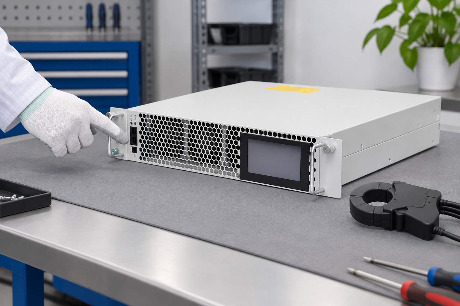
The product-reference illustration shows a closed unpowered module. It does not display a verified open-loop or closed-loop circuit. Establish the actual sensing arrangement from the approved drawing and site records, then plan any necessary physical verification with qualified personnel.
Evaluate dynamic behavior with a defined test
Feedforward is not automatically faster, and feedback is not automatically more accurate in every installation. Sensor quality, processing delay, current tracking, output limits, load changes, and system impedance all contribute to observed behavior. A label cannot substitute for a documented performance test.
Describe the load event you need the filter to handle. A steady rectifier load, a rapidly changing drive load, and an intermittently switched group of loads present different verification questions. Decide whether the priority is steady harmonic reduction, recovery after a load change, stable parallel operation, or a combination of those objectives.
Record source and load currents, filter state, and representative operating intervals using suitable instruments. Where an authorized test changes a load or operating mode, retain the event timing and configuration. Compare the same measurement boundary before and after the event. Do not compare a stable period in one test with an unrelated transient in another.
The AHF response-time guide helps separate a declared response parameter from a practical measurement. Any supplier claim should state the test conditions, measurement point, load event, and acceptance measure rather than only a small time number.
Review saturation and current allocation
Every practical filter has a permitted output capability. If the compensation demand exceeds that capability, an estimated feedforward command cannot be fully delivered, and a feedback controller cannot reach an impossible residual target. The remaining harmonics then require a capacity or operating-priority review rather than an assumption that a different loop label solves the problem.
Identify which functions share current capability on the selected model. Reactive-current compensation or imbalance correction may be enabled alongside harmonic control. Document priorities and actual per-phase demand. A total rating can hide a phase-specific limit or an operating condition that reduces available output.
Review protective events and thermal conditions as part of the same assessment. Do not raise undocumented settings or disable limiting functions to demonstrate better performance. The required solution may involve correcting sensing, revising approved priorities, restoring cooling, or selecting additional capacity after a load study.
Account for parallel filters and changing boundaries
Where several filters share a bus, establish whether each controller observes the same loads and compensation branches. The approved coordination design should explain which signals are shared and which units act independently. A simple block diagram is especially useful when the plant has expanded since commissioning.
Record the effect of adding or removing a module, switching capacitor stages, transferring supply, or connecting another nonlinear load. These changes can alter both the disturbance and the observed residual. An unexplained improvement during one arrangement does not prove the system will remain stable in every planned configuration.
Avoid universal statements that parallel closed-loop filters always interact badly or that feedforward systems never interact. Those outcomes depend on the actual implementation and network. Request documented coordination guidance and verify the installed configuration under representative operating conditions.
Write a specification that can be verified
Specify the measurement boundary, expected load spectrum, supply conditions, three-wire or four-wire requirements, enabled compensation functions, and available expansion arrangements. Ask the supplier to provide the supported sensing modes and an approved connection diagram for the proposed system.
Define performance using measurable results at the agreed point. Include harmonic currents in amperes, relevant voltage distortion, representative loading, and the agreed evaluation period. The IEEE 519 standard information supports the distinction between a filter’s local behavior and harmonic-control evaluation at the system boundary.
Require settings and event records to accompany commissioning results. A statement that the equipment is closed loop does not demonstrate a passed test. Similarly, a low THD screenshot without load and meter-point information is not a reproducible acceptance record.

Document the chosen operating mode, the reason it fits the installation, and the checks needed after future changes. This makes the selection maintainable: another engineer can understand the intended boundary without reverse-engineering a controller menu years later.
Safe verification and further learning
CT work and live electrical measurement require qualified personnel, rated equipment, and the site’s approved procedure. Never open a CT secondary while its primary carries current. Do not change sensor wiring or polarity while experimenting with a controller setting. Follow the manufacturer’s documentation and verified safe isolation arrangements.
The NPTEL IIT Delhi lesson below explains standards and monitoring relevant to assessing the result of a control strategy. It supplements the measurement discussion. It does not identify the internal algorithm of the pictured CNBYG unit or provide an installation diagram.

Watch Power Quality: Standards and Monitoring
Frequently asked questions
Does open loop mean an AHF has no feedback control?
No. The term may refer to the external harmonic compensation relationship. The converter can still have internal current regulation and DC-link voltage control. Identify the particular loop and controlled quantity before interpreting the label.
Is closed-loop AHF control always the better choice?
No universal ranking follows from the label. Review supported sensing arrangements, dynamic behavior, current limits, coordination, and documented performance under the intended load conditions. Select the implementation that can meet a defined verification requirement.
Can I move the CT to change from open loop to closed loop?
Do not assume that is supported. Sensor placement must match the exact model’s algorithm and approved configuration. A physical relocation can create incorrect feedback or phase association if it is not part of a documented design.
How should the selected strategy be accepted on site?
Use the agreed measurement point, representative load states, documented settings, and suitable instruments. Retain source, load, and filter observations where required, and evaluate both the target harmonic result and stable operation through relevant changes.