Where to Install Power Quality Meters in a Plant
Power quality meter location should follow the question the measurement must answer. Use an agreed incoming measurement point to assess the plant’s overall supply or harmonic boundary, relevant feeders to identify load contributions, and sensitive-equipment buses to investigate the voltage actually reaching affected loads. A single meter cannot necessarily answer all three questions. Mark candidate positions on the single-line diagram, document which loads and compensation devices each point includes, and select instrument capabilities for the required evidence. This guide explains where to measure without suggesting that every installed power meter can record every power-quality phenomenon.
Start with the complaint and measurement boundary
Write the complaint in a form that can be investigated: a production line trips during a voltage event, incoming current distortion rises during a process, or reactive demand changes after a new load is connected. A vague request to monitor everything encourages expensive instrumentation without a clear interpretation plan.
Identify the quantity and time behavior involved. A slow trend in energy or reactive demand requires different evidence from a brief voltage sag, transient, or harmonic-spectrum change. The placement and recording method must both match the problem. A correctly located meter with unsuitable capture capability can still miss the event.
The CNBYG multifunction power-instrument product page provides the relevant installed-meter context. Confirm the exact model’s supported measurements, recording functions, accuracy, and communication options. The reference image of a panel instrument does not establish Class A measurement, transient capture, or the capabilities of a specialist analyzer.
Use the incoming point for the overall plant question
An incoming location can show the combined behavior of the installation represented by that connection. It is useful for examining total demand, overall voltage trends, and source-current harmonics when the instrument supports the required measurements. Record which transformer, supply, or parallel connection is included.
If a formal assessment refers to the point of common coupling, agree on that point with the responsible project or utility engineer. The main switchboard is not automatically the accepted PCC in every installation. A convenient panel location should not silently redefine the boundary of an acceptance test.
An incoming measurement also combines the effects of many loads. It may show when a problem occurs without identifying which process contributes to it. Use feeder measurements and operating logs to narrow the source where necessary, rather than attributing the total distortion to the nearest machine.
Select feeders that divide the uncertainty
Prioritize feeders serving major nonlinear loads, rapidly changing processes, significant reactive demand, or equipment associated with the complaint. The objective is not to install a meter on every outgoing circuit. Choose points that distinguish competing explanations and support an engineering decision.
For example, if two production areas operate on different schedules, feeder records can help determine which operating period aligns with an incoming harmonic increase. That correlation is evidence for further investigation, not proof of causation. Other loads, supply conditions, and compensation states must still be considered.
Document which branches lie downstream of each sensor position. A feeder label can become outdated after plant modifications. Check the current approved diagram and maintenance records so a monitoring point does not unintentionally include another process or omit the suspected load.
Measure near sensitive equipment for voltage complaints
A voltage event recorded at the incoming board does not necessarily describe the voltage at a sensitive machine. Cable impedance, local connections, transformer arrangements, and branch switching can change the condition at the equipment bus. Place an appropriate instrument close enough to observe the actual supply relevant to the complaint.
Where the investigation requires separating upstream and local effects, compare synchronized recordings at an upstream reference and the sensitive-load location. Record configuration, time alignment, and instrument capability. Two unsynchronized screenshots may appear related even when they describe different events.
Do not assume that a meter displaying RMS voltage will capture a short event or transient. Establish the required time resolution, triggering, storage, and measurement method before deployment. The IEC 61000-4-30 standard page identifies a reference for power-quality measurement methods; actual instrument suitability must be checked against the intended assessment.
A practical location-selection table
| Investigation question | Candidate measurement point | What the point cannot establish alone |
|---|---|---|
| How does the overall plant behave? | Agreed incoming boundary | The contribution of each individual feeder |
| Which process contributes to a recurring issue? | Relevant process feeders | The exact internal source without further evidence |
| What voltage reaches a sensitive machine? | The machine’s supply bus | Whether the event originated upstream |
| Is compensation improving source current? | The agreed source-side boundary | Load-current waveform improvement at every machine |
| What changes during supply transfer? | Relevant buses under each planned supply | Performance of unobserved alternative arrangements |
| Where should permanent monitoring remain? | Points that support ongoing decisions | Events outside instrument capture capability |
These are measurement-planning options, not installation instructions. Physical connections require qualified personnel, rated equipment, appropriate protection, and the site’s approved electrical procedure. Select the evidence needed first, then design a safe means of obtaining it.
Place current sensors around the intended boundary
For harmonic investigations, distinguish load current, source current, and compensation-branch current. A shunt filter can supply harmonic current locally while a nonlinear load still draws a distorted waveform. Measuring only the load cable may therefore miss the improvement at the upstream source boundary.
Document CT or current-probe location, ratio, orientation, phase association, and the circuits enclosed by the sensor. Check the instrument’s configured topology and current range. An accurately measured signal can be misinterpreted if its phase reference or scaling is wrong.
The AHF CT placement guide addresses the filter’s own control sensors. An independent monitoring sensor serves a measurement purpose and should not be confused with the controller’s approved sensing arrangement. Do not move either sensor simply to obtain a more favorable displayed percentage.
Never open a CT secondary while its primary carries current. Follow the installed CT documentation and approved shorting arrangements for any necessary work. This article explains how to define a boundary, not how to improvise connections in an energized panel.
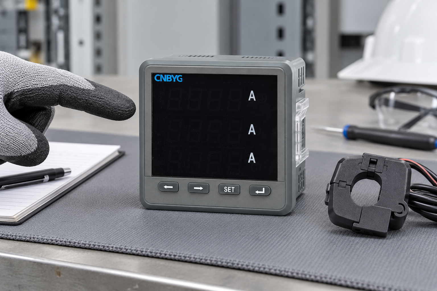
The illustration shows the real product family as an unpowered reference instrument. It does not show a live installation or a verified current-sensor connection. Confirm the exact unit’s measurement functions before relying on it for a power-quality study.
Account for generators, bus ties, and alternate supplies
A plant may have more than one normal operating configuration. A meter that represents the installation when a bus tie is open may observe a different combination of loads when it is closed. Record each planned arrangement and how the measurement boundary changes.
Generator operation can also change the supply and compensation environment. Decide which source and downstream points are needed to understand the specific operating question. Do not assume that an incoming utility meter captures the generator-fed part of the plant during an islanded interval.
Mark unobserved configurations explicitly in the report. If an alternative arrangement was not operated during the study, record that limitation instead of treating a successful normal-supply recording as proof for every supply state. Future reviews can then target the missing condition efficiently.
Choose permanent and portable monitoring deliberately
Permanent monitoring supports trends and recurring operational decisions at selected points. Portable instruments can investigate temporary complaints, compare several feeders, or provide specialist capture capabilities. The choice depends on the question, required features, safe access, data retention, and frequency of investigation.
The portable vs fixed power-quality monitoring guide explains that equipment choice. The industrial power-quality survey procedure covers the broader study workflow. This article focuses on the spatial coverage that those studies need.
Avoid treating permanent placement as permanent adequacy. New loads, changed production, or a different complaint may require another measurement point or instrument. Review the location plan when the electrical distribution or the purpose of monitoring changes.
Make recordings comparable across locations
Use a shared time reference and record the instrument configurations. Preserve voltage and current references, aggregation intervals, harmonic bandwidth where relevant, event thresholds, and operating logs. Without those details, differences between points can reflect recording settings rather than electrical behavior.
Label files with the physical point and operating configuration, not only an instrument serial number. Include the sensor ratios and the installation diagram revision. Retain original recordings as well as exported charts so another engineer can revisit the interpretation.
Where measurements are not simultaneous, explain the load and supply differences between intervals. A feeder measured during an idle period cannot be directly compared with an incoming point measured during full production without accounting for those conditions. Use the limitation to guide additional recording rather than conceal it.
Turn the location plan into a useful deliverable
For each chosen point, state the question, measured quantities, required instrument capability, expected operating states, safe access arrangement, and review responsibility. Explain why the point was selected and what remains outside its boundary. That makes the plan useful to both the installer and the analyst.
After collecting data, check whether the evidence actually resolves the original question. If all locations show the same upstream voltage event, unnecessary feeder expansion may add little value. If one feeder differs, targeted follow-up can be more useful than indiscriminate monitoring across the site.
The NPTEL power-quality course syllabus provides educational context for the scope of power-quality studies. The lesson below explains standards and monitoring. Neither source certifies the pictured panel instrument for every measurement described here.

Watch Power Quality: Standards and Monitoring
Frequently asked questions
Is the main incoming board always the best meter location?
It is useful for overall installation behavior, but it may not identify individual load contributions or the voltage at a sensitive machine. Choose points according to the investigation question and agree on any formal acceptance boundary separately.
Do I need a meter on every feeder?
Usually the decision should be evidence-driven rather than based on blanket coverage. Prioritize points that distinguish plausible causes, represent significant loads, or support ongoing operational decisions. Expand monitoring where the initial records leave a specific uncertainty.
Can a multifunction panel meter replace a power-quality analyzer?
Only if the exact model provides the capabilities required for the intended measurement. A voltage or THD display does not automatically establish event capture, transient recording, measurement class, or adequate storage and time resolution.
How should I compare measurements from two locations?
Align time references, document instrument configuration and sensor scaling, and record comparable operating conditions. Identify what each point includes and preserve original recordings. Explain any nonsimultaneous periods or unobserved supply arrangements.