Harmonics from LED Lighting Systems
LED lighting harmonics are harmonic current components associated with the electronic drivers that supply LED lamps and luminaires. Their practical impact depends on driver design, operating level, circuit arrangement and the number of devices sharing the electrical system. Assess the installed lighting load rather than assuming that every LED product behaves alike. Measure current and voltage at relevant locations, investigate neutral loading where applicable, and distinguish harmonic effects from dimming behavior, poor connections or supply events before choosing mitigation.
This guide is for facility engineers and buyers evaluating commercial lighting installations. It addresses the evidence needed for procurement and troubleshooting without assigning an unsupported universal distortion limit. Electrical investigation must follow qualified-personnel requirements, approved safety procedures and the applicable installation rules.
Why driver design matters
LEDs require controlled electrical input, and the driver connects that requirement to the building supply. Its input behavior determines how current is drawn. Equipment with different input designs can have different harmonic performance even when lamp wattage or light output is similar.
Do not infer electrical input quality from efficiency, brightness or a marketing description alone. Obtain the actual driver or luminaire documentation, including the conditions under which reported power factor and distortion were measured. A specification at rated operation may not describe a different dimming level or control mode.
Keep the product identification precise. Replacement drivers, mixed fixture batches and later fit-outs can change the installed load. A lighting schedule that lists only nominal watts may omit the driver information needed for an electrical assessment. Record model, quantity, supply arrangement and operating conditions where available.
Separate harmonic current from visible lighting symptoms
Flicker, dimming instability or a lamp failure does not automatically demonstrate a harmonic problem in the supply. These symptoms can involve driver compatibility, controls, connection condition, local voltage behavior or equipment faults. Investigate the symptom with the lighting supplier and the electrical measurements together.
Similarly, a harmonic current reading does not establish that the lighting is the dominant cause of a building-wide complaint. Other electronic supplies and drives may contribute. Compare lighting feeders with upstream records and representative operation of other loads before assigning responsibility.
Describe the complaint concretely. Record affected areas, timestamps, dimming settings, switching events and recent replacements. An event that occurs only at a particular control level suggests a different investigation from one affecting several unrelated circuits simultaneously.
Read the specification with its test conditions
Ask whether the reported data apply to the complete luminaire or a driver under a specified laboratory load. Confirm input voltage, frequency, operating level and other relevant conditions. Numbers from different conditions may not form a fair procurement comparison.
Power factor and current distortion describe related but different aspects of electrical input. A favorable value for one quantity should not be used as a substitute for the other. The actual network assessment may also require harmonic components rather than only a total percentage.
The IEC 61000-3-2 publication provides a relevant starting point for equipment harmonic current emission requirements within its stated scope. Confirm the current edition and whether the product and assessment fall within that scope. A product test requirement should not be transferred unchanged into a whole-building acceptance limit.
| Procurement or investigation item | Information to request | Why it matters | Avoid assuming |
|---|---|---|---|
| Product identity | Driver and luminaire model, quantities and replacement history | Establishes what is actually installed | All fixtures of equal wattage behave the same |
| Operating condition | Rated and relevant dimmed operation data | Electrical input may change with controls | One rated-load number covers every setting |
| Current behavior | Distortion and harmonic components under stated conditions | Supports circuit and aggregation assessment | THD alone determines mitigation capacity |
| Power quantities | Input power and relevant power factor definition | Separates different input characteristics | Power factor proves absence of harmonics |
| Compliance evidence | Applicable standard, edition and test report scope | Supports a specific product claim | Product compliance guarantees building compliance |
| Site measurement | Circuit and upstream records during actual operation | Captures installed interaction with other loads | Laboratory data replace all site investigation |
Use this as an information checklist. It contains no fabricated performance limits and should be adapted to the installation and adopted requirements.
Measure at circuit and upstream locations
Map lighting distribution before placing instruments. Identify single-phase circuits, three-phase boards, shared neutrals where applicable and upstream supply points. Confirm that the diagram reflects later fit-outs and changes to lighting controls.
A circuit measurement describes that circuit. An upstream recording includes other connected loads and the effect of aggregation. Synchronized measurements help investigate contributions without comparing unrelated operating periods. The meter placement guide explains the boundary choices.
Record representative operating levels. Include switching patterns and relevant dimming conditions if the complaint concerns them. Avoid choosing only a convenient full-output test when normal use is substantially different. State operating modes that were absent during the survey rather than treating missing evidence as a pass.
Choose instruments whose documented functions and ratings suit the investigation. Ordinary indication should not be assumed to implement every harmonic or event measurement method. Temporary electrical connections and sensor arrangements require approved procedures and suitable equipment.
Interpret percentages alongside actual current
Total current distortion is useful, but it needs load context. A relatively large percentage at a light-load condition may correspond to less absolute harmonic current than a smaller percentage on a much larger load. Retain fundamental current, RMS current and relevant components alongside the percentage.
The harmonic spectrum guide explains why individual components can matter. Changes in the spectrum with dimming or switching provide evidence about the installed behavior, but they do not alone establish a network remedy.
For harmonic measurement methods, consult the applicable IEC 61000-4-7 publication. Aggregation and grouping affect comparison of results. Record method settings and instrument information when comparing supplier data, feeder measurements and before-and-after results.
Investigate neutral loading separately from phase balance
In three-phase four-wire distribution, selected harmonic components can add in the neutral. Equal fundamental loading across phases therefore does not prove that neutral current is low. Measure neutral RMS current and harmonic content where relevant to the complaint and installation.
Assess conductor arrangement, connections and installation conditions as well as current. A hot connection may need repair regardless of the harmonic profile. A thermal image is evidence of temperature under the observed condition; it is not a complete explanation of the electrical mechanism or conductor acceptability.
The existing neutral harmonic investigation discusses the distinction between balancing fundamental loads and understanding harmonic components. Adapt that measurement logic to the actual lighting distribution without assuming the building has the same loads as a data center.
Distinguish current emissions from supply voltage quality
Harmonic current interacts with network impedance and other loads. The voltage seen by a lighting circuit therefore depends on the broader system, not just the current drawn by its own drivers. Measure voltage behavior at the affected location and relevant upstream points when investigating supply compatibility.
If several unrelated load groups experience a disturbance together, investigate the shared supply event. If the complaint occurs only at one fixture or control channel, local equipment and control compatibility may be more relevant. Keep both possibilities open until the records support a specific cause.
The IEC 61000-4-30 publication addresses power quality measurement methods. Confirm which methods and instrument evidence are needed for the project. A laboratory emission report and a building power quality survey answer different questions and should retain their separate scopes.
Choose corrective action from the established cause
Correct confirmed defects and incompatible equipment first. A failed driver, unsuitable dimming arrangement or damaged connection requires the appropriate lighting or electrical repair. A building harmonic filter should not be proposed as a substitute for those actions.
Where harmonic current mitigation is justified, evaluate the CNBYG active harmonic filter for the actual supply, load profile and sensing arrangement. Selection needs the harmonic current components, representative operating range and manufacturer application confirmation. Luminaire count or total lighting wattage alone cannot determine the correct filter rating.
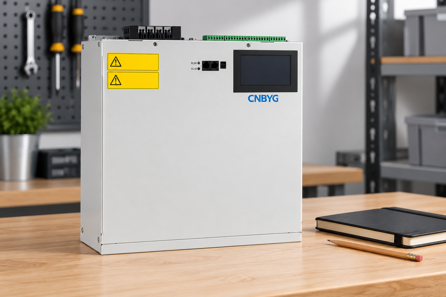
The image is an exterior product-reference illustration. It does not show installation wiring or verified performance. Safety sticker text is simplified to pictograms; actual product labels and approved instructions govern equipment handling.
Review the distinction between harmonic filtering and reactive compensation. A low power factor reading needs its measurement definition and relevant power quantities. Adding capacitors blindly to a distorted system can introduce an unsuitable network interaction. Obtain an engineering assessment rather than assuming one device resolves every measured quantity.
Verify results after lighting changes or mitigation
Set acceptance conditions before changing the installation. Include measurement points, methods, representative lighting levels and the original symptoms. If the issue concerns a shared supply, a test at one corrected fixture does not establish building-wide performance.
Compare before-and-after recordings under reasonably comparable operation. Record replaced drivers, fixture quantities, control settings and other load changes. Distinguish an improvement attributable to the intervention from a difference caused by a lighter operating period.
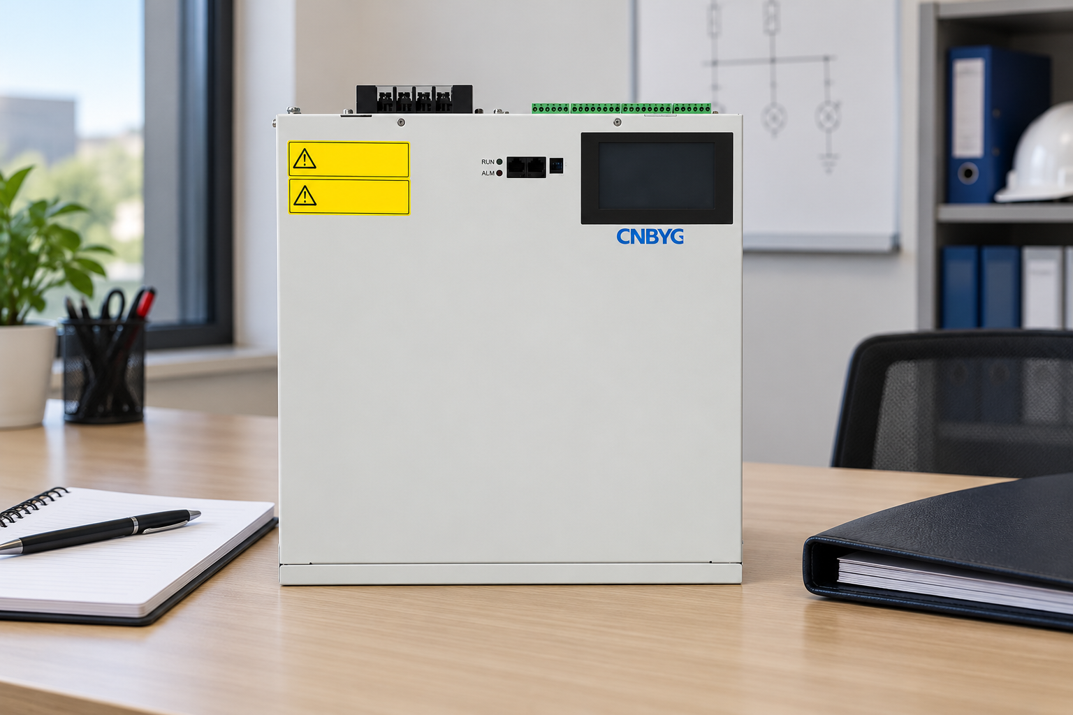
Keep the procurement evidence, site records, settings and maintenance information together. Later replacement batches may have different electrical behavior even if their lighting appearance is similar. Review relevant measurements when substantial changes occur or the original symptoms return.
Further learning: power quality monitoring
The NPTEL lecture below introduces general standards and monitoring concepts. It helps explain why measurement methods and assessment boundaries need to be specified. It does not replace a lighting product test report or certify the illustrated filter for a particular installation.

Watch Power Quality: Standards and Monitoring
Frequently asked questions
Do LED lights always cause unacceptable harmonics?
No. Driver design, operating conditions and the installed network determine the result. Review product evidence and actual circuit measurements rather than applying one conclusion to every LED installation.
Does high power factor mean there are no harmonics?
No. Power factor and harmonic current information describe different aspects of input behavior. Obtain the relevant definitions, operating conditions and harmonic evidence instead of substituting one value for the other.
Can balanced lighting circuits still load the neutral?
Yes, selected harmonic components can add in a three-phase four-wire neutral. Fundamental phase balance does not prove low neutral current. Measure current and assess installation conditions with qualified personnel.
What should be checked after replacing a large lighting batch?
Confirm driver identity, operating settings and circuit arrangement, then compare representative current and voltage records where required. Retain product test scope and site acceptance requirements separately.