Capacitor Bank Ventilation Calculation: Heat Loss, Airflow and Fan Selection
A capacitor bank ventilation calculation starts with documented heat loss in watts, the temperature of the air actually entering the cabinet, and an allowable internal air-temperature rise derived from component requirements. A preliminary forced-air estimate is V = 3600P/(ρcpΔT), with V in m³/h, heat P in W, air density ρ in kg/m³, specific heat cp in J/(kg·K), and temperature rise ΔT in K. The result is a heat-balance estimate, not a fan purchase rating. Filters, grilles, internal restrictions, altitude and local hot spots must still be checked.
Build a heat-loss inventory, not a kvar shortcut
List capacitors, detuning reactors, switching devices, busbars, protective components, controllers and auxiliaries within the thermal boundary. Obtain their applicable loss data from the suppliers. Use the intended operating conditions: the number of active stages, harmonic duty, electrical current and ambient conditions can affect the heat that must leave the enclosure.
Reactive power in kvar is not heat loss in watts. A large capacitor bank does not automatically dissipate its rated reactive power as heat. Applying an invented fixed watts-per-kvar multiplier to every assembly can miss reactor losses or misrepresent a different capacitor design. If component losses are unavailable, retain the gap in the calculation and request them rather than turning a purchasing assumption into a product specification.
Account for external gains separately. A cabinet exposed to solar radiation, a hot neighbouring enclosure or a heated process area may require a broader thermal assessment. Heat rejected through enclosure walls can also matter. The simple calculation below assumes that the stated heat load is the portion to be removed by ventilation; it does not simultaneously claim an unverified wall-cooling credit.
For the general equipment context, use the capacitor bank overview. This page focuses on thermal calculation and fan selection rather than electrical kvar sizing.
Establish the real inlet-air condition
Measure or specify the air temperature at the planned intake location. The outdoor weather report or the temperature at the building entrance may not represent the air beside a hot switchboard. Include realistic seasonal conditions and the room’s own heat rejection. Moving heat from a cabinet into an already hot room does not remove it from the building.
Derive the allowable cabinet air temperature from the equipment requirements, installation arrangement and local component environment. A capacitor’s case temperature, a reactor winding temperature and the bulk exhaust-air temperature describe different things. A single enclosure sensor cannot demonstrate that every component remains within its permitted condition.
The difference between the design inlet temperature and the allowable internal air temperature gives the preliminary air-temperature rise. If there is no positive temperature margin, increasing ventilation alone cannot make the inlet air colder. Reconsider the room condition, equipment arrangement, heat load or a suitable cooling method rather than entering a negative temperature rise into the formula.
Apply the steady-state heat balance
For sensible heat carried away by air, P = ṁcpΔT, where ṁ is mass flow in kg/s. Volumetric flow is mass flow divided by density. Multiplying cubic metres per second by 3600 converts the result into cubic metres per hour. These relationships produce the opening formula when the air properties and heat load are expressed in the stated units.
NASA’s explanation of mass flow rate describes the relationship between density and moving air volume. The NPTEL introduction to convection distinguishes heat transfer through moving fluid from other mechanisms. Together they provide physics background for the calculation; neither source specifies a CNBYG fan size or approves a capacitor cabinet layout.
The preliminary equation assumes steady conditions, a defined heat load and a useful average temperature rise across the airflow. It does not resolve recirculation, bypass, strongly uneven flow, transient stage operation or the temperature difference between a component surface and adjacent air. Those limitations must remain visible when the result is passed to the enclosure designer.
Worked example with declared assumptions
Assume an illustrative 600 W heat load assigned to ventilation, air density of 1.2 kg/m³, specific heat of 1000 J/(kg·K), and an allowable air-temperature rise of 10 K. These are rounded calculation assumptions, not measured CNBYG losses or guaranteed site air properties. The heat load must be replaced by the actual assembly’s verified value.
The calculation gives V = 3600 × 600 /(1.2 × 1000 × 10) = 180 m³/h. This means that the idealised heat balance needs that actual airflow through the intended thermal path. It does not mean that a fan advertised at 180 m³/h in free air will deliver the requirement after installation.
If the available temperature rise falls to 5 K while the other assumptions remain unchanged, the estimate doubles to 360 m³/h. This sensitivity shows why ambient conditions matter. It also shows why the margin should be derived honestly: choosing an unrealistically large allowed temperature rise merely makes the calculated fan appear smaller.
| Design input | Evidence needed | Effect on the decision |
|---|---|---|
| Heat assigned to ventilation | Component loss schedule and operating duty | Determines the heat to be transported |
| Inlet temperature | Site design condition or representative measurement | Limits the available temperature rise |
| Air density | Appropriate site pressure and temperature basis | Changes mass carried by each cubic metre |
| System resistance | Filters, grilles and internal path information | Determines the installed fan operating point |
| Component limits | Supplier instructions and assembly assessment | Constrains air temperature and local layout |
This table is a calculation-input checklist. The illustrative values above should not be copied into a project specification without replacing them with the project’s own evidence.
Select the fan at an installed operating point
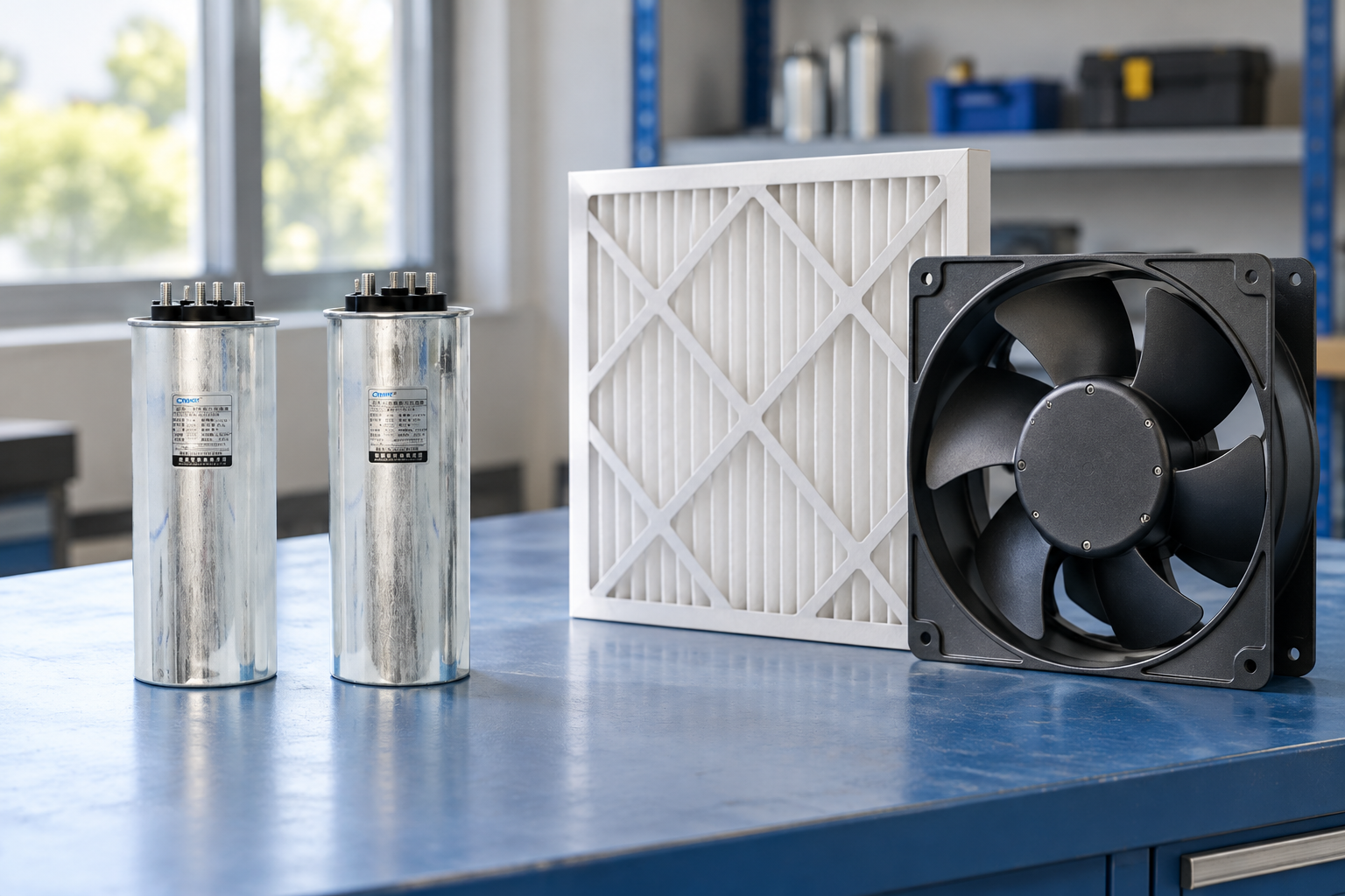
A fan curve relates airflow to pressure. The installed system also has a resistance characteristic. Their intersection determines the approximate operating flow, rather than the free-air number printed prominently in a catalogue. Include the intake, exhaust, filter, grille and internal path when assessing resistance.
Ask for the proposed fan’s curve at the relevant supply and operating conditions, and for the pressure-drop basis used for the enclosure path. Define both clean and service-condition filter assumptions. An unspecified percentage allowance on airflow does not replace a pressure-drop assessment, particularly where fine filtration or a restrictive arrangement is needed.
Check the assembly’s electrical and environmental requirements as well. Fan supply, control logic, alarm contact, protection, access for replacement and filter-service method all affect reliability. The selected arrangement must preserve the required enclosure performance. Cutting additional holes to meet a thermal target can compromise another design requirement and therefore needs an assembly-level review.
Make airflow pass the components that need it
A useful airflow path takes incoming air through the heat-producing region and carries it out without immediately drawing it back into the intake. A fan placed close to an exhaust opening can move plenty of air while bypassing the capacitor compartments. Internal barriers and cable bundles can also leave a reactor or terminal region poorly served.
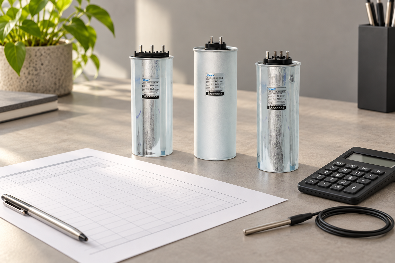
Follow the capacitor and reactor manufacturers’ spacing and mounting instructions. The product-reference photographs here show disconnected components and planning props; they are not an approved assembly drawing. A visually tidy row of components does not establish sufficient local cooling or safe electrical separation.
Where detuned reactors contribute substantial heat, consider their effect on adjacent components and the overall path. The reactor temperature-protection guide explains a related monitoring issue. Temperature protection can detect certain abnormal conditions, but it does not make a deficient normal cooling design acceptable.
Treat altitude, contamination and moisture as separate inputs
Lower air density changes the mass transported by a given volumetric flow. Use appropriate site conditions and obtain any required component or fan derating from the relevant supplier. A sea-level fan figure should not be accepted as proof of performance at a high-altitude site. The capacitor bank altitude guide addresses wider installation implications.
Dust accumulation changes both the filter resistance and heat transfer from surfaces. Define a service strategy based on actual exposure and condition monitoring rather than inventing a universal replacement interval. Include safe access for inspection and a means of identifying cooling-system failure before temperatures become unacceptable.
Ventilation can also bring humid air into an enclosure. It is not automatically a remedy for condensation, especially when equipment is cold after a shutdown. The thermal and moisture questions need compatible decisions; a design that removes operating heat may still need separate measures for storage or idle periods.
Validate the completed cabinet under representative duty
Commission with the enclosure in its normal service condition, including doors, covers and filters. Record inlet, outlet and representative internal temperatures, the active stage combination, supply conditions and relevant electrical loading. A short test with the door open cannot validate normal closed-door cooling.
Allow the assessment to address thermal stabilisation and the worst credible operating combination. Compare local component conditions with their applicable requirements, not solely with the average exhaust-air rise used in the preliminary model. If heat loss or duty differs from the calculation, update the model and review whether the result still covers the actual installation.
For a CNBYG BSMJ capacitor enquiry, provide the assembly layout, capacitor and reactor schedule, environmental conditions, intended ventilation path and available loss information. Request model-specific installation and temperature requirements. A component purchase and a complete cabinet thermal assessment are related but distinct engineering decisions.
Further learning: forced convection
The NPTEL IIT Bombay lecture below explains forced convection. It helps readers understand how moving air carries heat, while the actual cabinet requires its own documented assessment and verification.

Frequently asked questions
Can I size a capacitor bank fan from kvar alone?
No. Obtain the heat losses of the actual capacitors, reactors, switching devices and other internal equipment under the intended duty. Reactive power and thermal loss are different quantities.
Is the calculated airflow the fan’s catalogue rating?
No. The calculation estimates required useful airflow. Select and verify the fan at the installed operating point with the expected resistance of filters, grilles and the internal path.
Will a larger fan cool below room temperature?
Ordinary ventilation using room air cannot provide an inlet temperature below that air source. If ambient air leaves insufficient temperature margin, another aspect of the thermal design must change.
What should be checked after installation?
Verify temperatures under representative closed-door operation, including local component conditions, inlet air, stage duty and filter condition. Compare those results with the equipment requirements and preserve the calculation and commissioning record together.