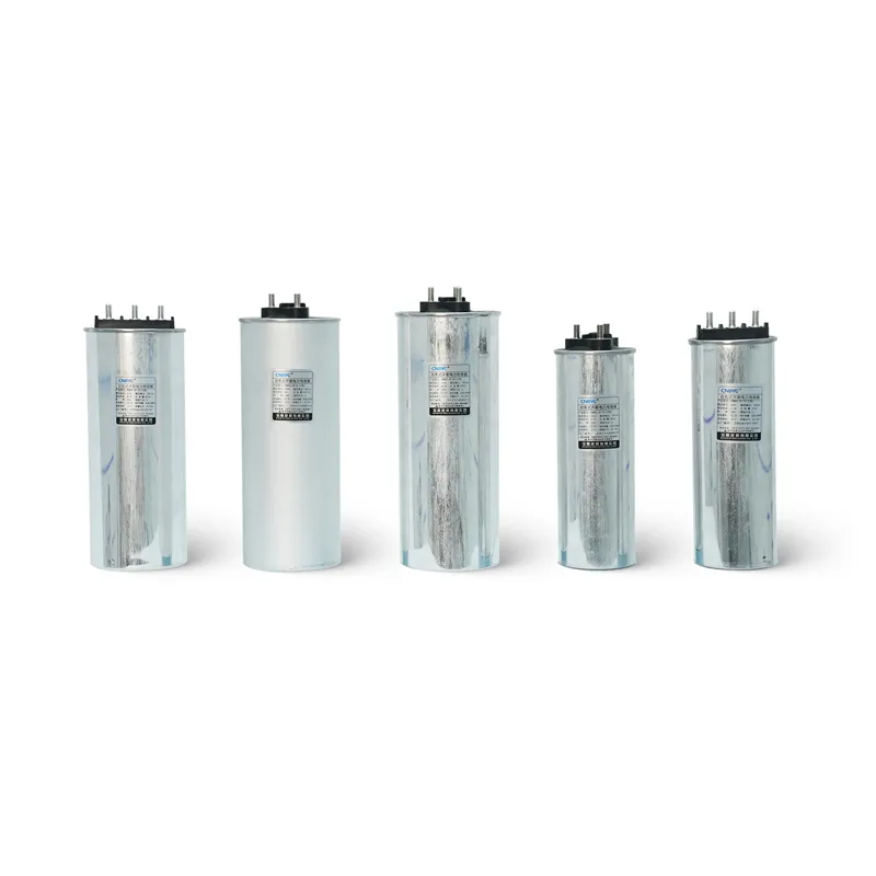


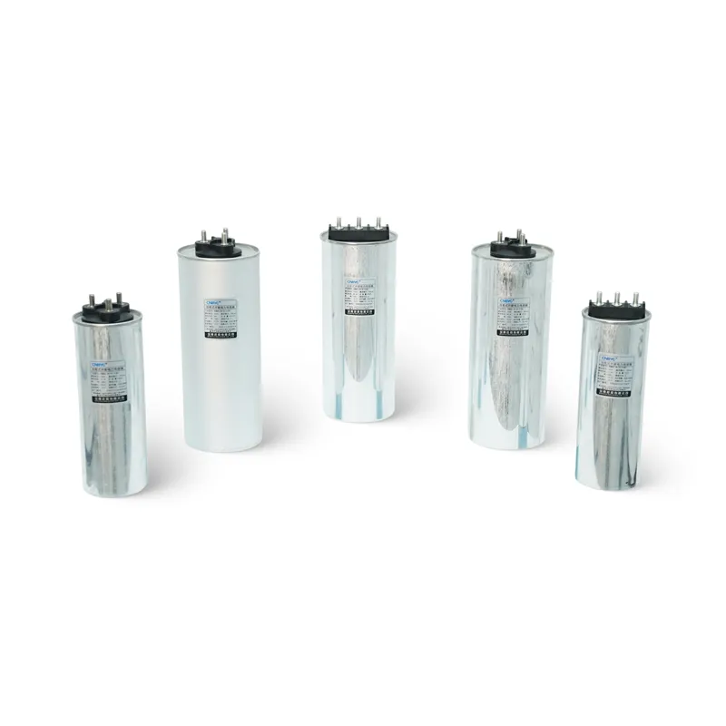
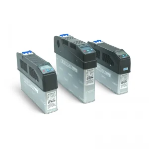
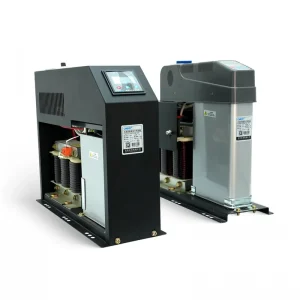
BSMJ (Cylinder) Series Cylindrical Capacitors
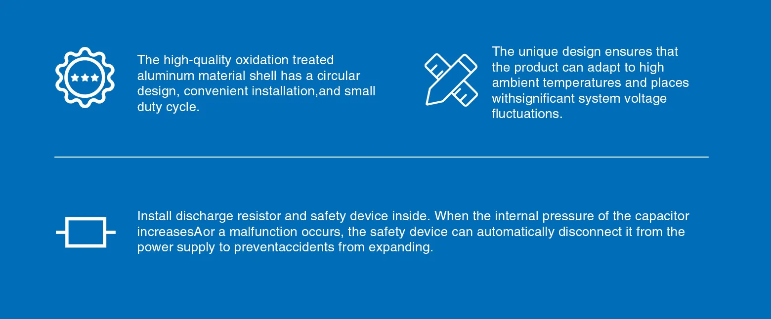
BSMJ (Cylinder) Series Cylindrical Capacitors feature high-quality anodized aluminum shells with a round design for easy installation and minimal space requirements. Their unique design allows them to withstand high ambient temperatures and significant system voltage fluctuations. Internally equipped with a discharge resistor and safety device, the safety device automatically cuts off power to prevent escalation in the event of increased internal pressure or failure of the capacitor.
Product Description
The BSMJ(cylinder)series cylindrical capacitors are suitable for power frequency AC power systems with a nominal voltage of 1000V and below, to improve power factor, reduce reacive power loss, and improve voltage quality.
Main Technical Parameters
| Project | Parameter | |
| Loss angle tangent value | Below 0.0012 at rated power frequency voltage | |
| Capacitance deviation |
The difference between the measured value and rated value of the capacitor shall not exceed O~+10%, and the ratio of the maximum to minimum capacitance measured between any two line terminals in a three-phase capacitor shall not exceed 1.08 |
|
| Withstand voltage |
Inter polar | Power frequency 2.15Un, 2S |
| Polar shell | Rated voltage of 600V and below, applied voltage of 3.6kV, 5S | |
| Rated voltage of 600V and below,applied voltage of 7.2kV, 5S | ||
| Maximum allowable over voltage | 1.1Un, not exceeding 8h every 24h | |
| Maximum allowable over current | 1.3In | |
| Self discharge characteristics |
The capacitor is equipped with a discharge device, which can reduce the remaining voltage of the capacitor from 2Un to 75V or below within 3 minutes of disconnecting the power supply |
|
| Executive standards | IEC60831-2017,GB/T12747-2014 | |
Main Specifications And External Dimensions
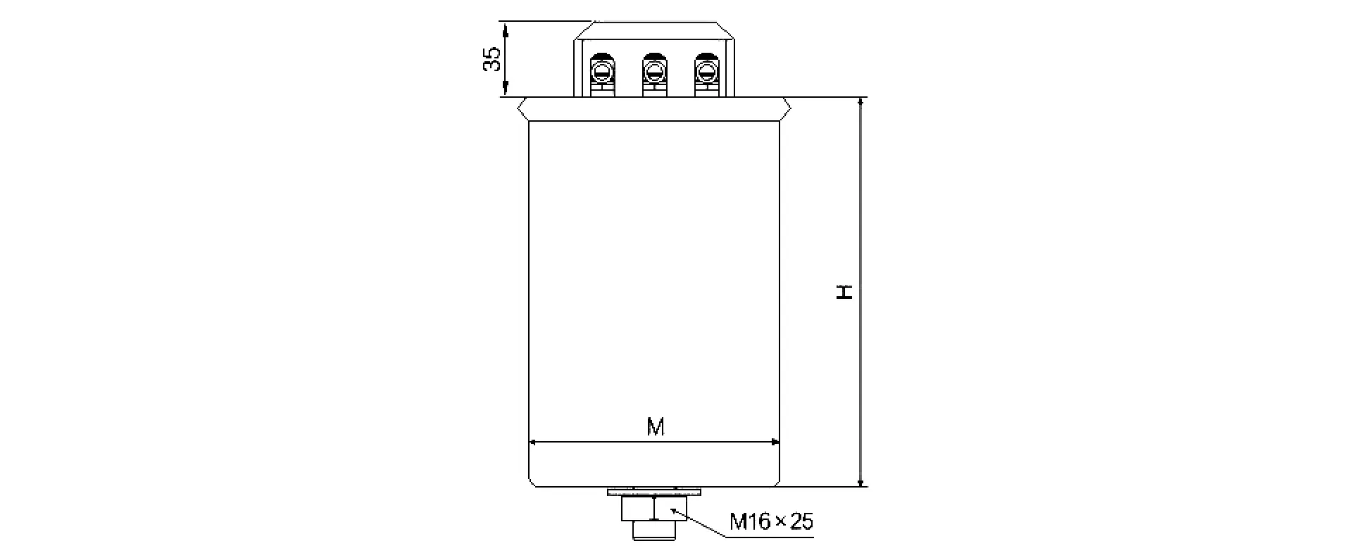
| Specifications | Capacity(μF) | Current(a) | Body size(mm) | Installation sole (mm) | |
| A | B | ||||
| 0.45-10-3 | 157.3 | 12.8 | 16 | 245 | M12x17 |
| 0.45-15-3 | 235.9 | 19.2 | 96 | 245 | M16x25 |
| 0.45-20-3 | 314.5 | 25.7 | 106 | 245 | M16x25 |
| 0.45-25-3 | 393.2 | 32.1 | 116 | 245 | M16x25 |
| 0.45-30-3 | 471.8 | 38.5 | 116 | 290 | M16x25 |
| 0.45-40-3 | 629.1 | 51.3 | 126 | 290 | M16x25 |
| 0.48-10-3 | 138.2 | 12.0 | 16 | 245 | M12x17 |
| 0.48-15-3 | 207.3 | 18.0 | 96 | 245 | M16x25 |
| 0.48-20-3 | 276.5 | 24.1 | 106 | 245 | M16x25 |
| 0.48-25-3 | 345.6 | 30.1 | 116 | 245 | M16x25 |
| 0.48-30-3 | 414.7 | 36.1 | 116 | 290 | M16x25 |
| 0.48-40-3 | 552.9 | 48.1 | 126 | 290 | M16 x25 |
| 0.525-10-3 | 115.5 | 11.0 | R | 245 | M12x17 |
| 0.525-15-3 | 173.3 | 16.5 | 96 | 245 | M16x25 |
| 0.525-20-3 | 231.1 | 22.0 | 106 | 245 | M16x25 |
| 0.525-25-3 | 288.9 | 27.5 | 116 | 245 | M16x25 |
| 0.525-30-3 | 346.6 | 33.0 | 116 | 290 | M16x25 |
| 0.525-40-3 | 462.2 | 44.0 | 126 | 290 | M16x25 |
| 0.525-50-3 | 577.7 | 55.0 | 136 | 290 | M16x25 |
Note: The external installation dimensions of single-phase products are the same as those of three-phase products of the same specification.
Our company can customize other specifications of products for users. If you have special requirements, please negotiate and place an order.
Instructions
Instructions for Use
- Transport in original factory packaging; handle carefully.
- Store in dry, non -corrosive gas indoor environment.
User acceptance inspection
- Check nameplate model matches purchased product before use.
- Capacity test: Conduct as per 4.2,using instruments with 2% relative error.
- Withstand voltage test: Apply 75% of the voltage specified in 4.3.
Installation and operation
- Install indoors, for use below 2000m altitude.
- Ambient temperature -25~+50C,humidity <85%; low-temperature version (-40~+50C)available on request.
- Installation site: avoid direct sunlight,rain,excessive dust and severe vibration; spacing >30mm; ensure good ventilation and heat dissipation in high summer temperatures.
- Before installation, consider voltage rise after capacitor input to prevent long-term operation under over voltage; check voltage waveform and network characteristics; take measures to limit harmonics if harmonic sources exist.
- When paralleled with induction motor, capacitor current <90% of motor no-load current. Use flexible copper wires for line and grounding terminals,ensure good contact; check terminals regularly to prevent damage.
- Interval between disconnection and reconnection >3min (self-discharge time) to avoid over voltage damage.
Ordering instructions
- Users must provide product rated voltage,rated capacitance, number of phases, and other parameters.
- Users should try their best to provide some characteristics of the place of use.
Manuals & Certificates
Related Products
Request a Custom Quote
Interested in this product? Fill out the form below and our sales team will get back to you within 24 hours.