APFC Generator Transfer Interlocks: Define and Test the Enable Logic
An APFC generator transfer interlock defines when automatic capacitor stages are permitted to operate as the installation changes between utility and generator supply. Begin with the generator manufacturer’s reactive-load limits and the approved transfer sequence. In many standby arrangements, utility-mode capacitor stages must be inhibited before transfer and remain unavailable on generator power unless a separately engineered operating mode is approved. Do not assume that a normal utility power-factor target is suitable for the generator, or that removing one controller supply guarantees every capacitor stage has opened.
Define the operating requirement before choosing contacts
An interlock is a system behavior, not simply an extra wire between two panels. The design must identify the source states, the required capacitor-bank state in each condition, how that state is achieved, and what evidence confirms it. A signal called generator running may exist before the generator supplies the bus. A signal called utility healthy may become true while the bus remains on generator power. Their names are insufficient to define the switching sequence.
This guide addresses the capacitor bank’s permission and inhibition logic around a transfer. It complements the broader power factor correction for generators guide. It does not provide a generic transfer-switch wiring diagram or approve connecting capacitors to any particular generator. Closed-transition, paralleled, and islanded systems require a sequence appropriate to their actual power-system design.
Understand why the generator changes the decision
Cummins’ T-030 generator application manual discusses leading-power-factor loads, including power-factor correction capacitors, and their potential to cause excitation and voltage-control problems. Use the delivered generator and alternator documentation for the permitted operating envelope. This is a reason to review the transfer arrangement; it is not a universal statement that the same capacitor capacity is unacceptable under every engineered generator operating condition.
The installation’s reactive balance changes with connected loads. A bank selected for a utility-fed plant may remain connected while the generator carries only essential equipment. Motor loading, UPS input behavior, and the restoration sequence can differ from the utility condition. Record which capacitor stages can physically remain connected to the transferred bus, including fixed compensation outside the main APFC enclosure. An interlock addressing only the visible automatic bank may leave other capacitance unaccounted for.
Map each signal to a physical state
Prepare the single-line diagram, the transfer-switch sequence, APFC control schematic, generator operating requirements, and stage list. For every source-status signal, identify its origin and what it actually proves. Distinguish a controller’s intended source selection from a transfer device’s confirmed position. Identify whether a status depends on control power that may disappear during an outage.
Document the final switching elements for all relevant capacitor stages. An APFC controller output, an interposing relay, and a main contactor are different points in the path. Where the design requires confirmed disconnection, state how the confirmation is obtained and its limitations. Do not describe a general panel lamp as proof of every stage’s power-circuit condition without supporting design evidence.
Create a cause-and-effect table
The following table illustrates questions for an approved sequence. It is not a ready-made control program: the required states, delays, and responses must be accepted by the generator, transfer, and compensation-system designers. Identify unknown or conflicting indications explicitly rather than assigning them the same behavior as normal utility operation.
| System condition | Compensation question | Evidence or signal to define | Acceptance point |
|---|---|---|---|
| Normal utility supply | Which automatic stages may be enabled? | Confirmed source position and valid measurement boundary | Bank follows the approved utility control mode |
| Transfer preparation | When must stages be inhibited or disconnected? | Transfer request and permitted sequence timing | Required stage state is achieved before the next transfer action |
| Bus supplied by generator | Is compensation prohibited or specially controlled? | Actual source position and approved generator mode | No unapproved utility-mode stage can reconnect |
| Unknown or conflicting source state | What is the specified protective response? | Status disagreement, missing signal or control-power loss | Defined safe behavior without an assumed healthy source |
| Utility restoration | What permits a return to utility compensation? | Completed transfer, valid measurements and discharge constraints | Re-enable occurs only after approved conditions are met |
| Manual mode or maintenance control | Can any command defeat a required inhibit? | Selector positions and all alternate command paths | Protective requirements remain effective in permitted modes |
Locate the inhibit at an effective control boundary
The correct arrangement depends on the installed equipment. Some designs use a documented controller inhibit input, while others remove a stage-enable path through an approved relay arrangement. Do not improvise by disconnecting arbitrary measurement wiring, manipulating a CT circuit, or changing the target PF to an extreme value. A workaround that appears to suppress switching may create misleading measurements or leave a manual command path active.
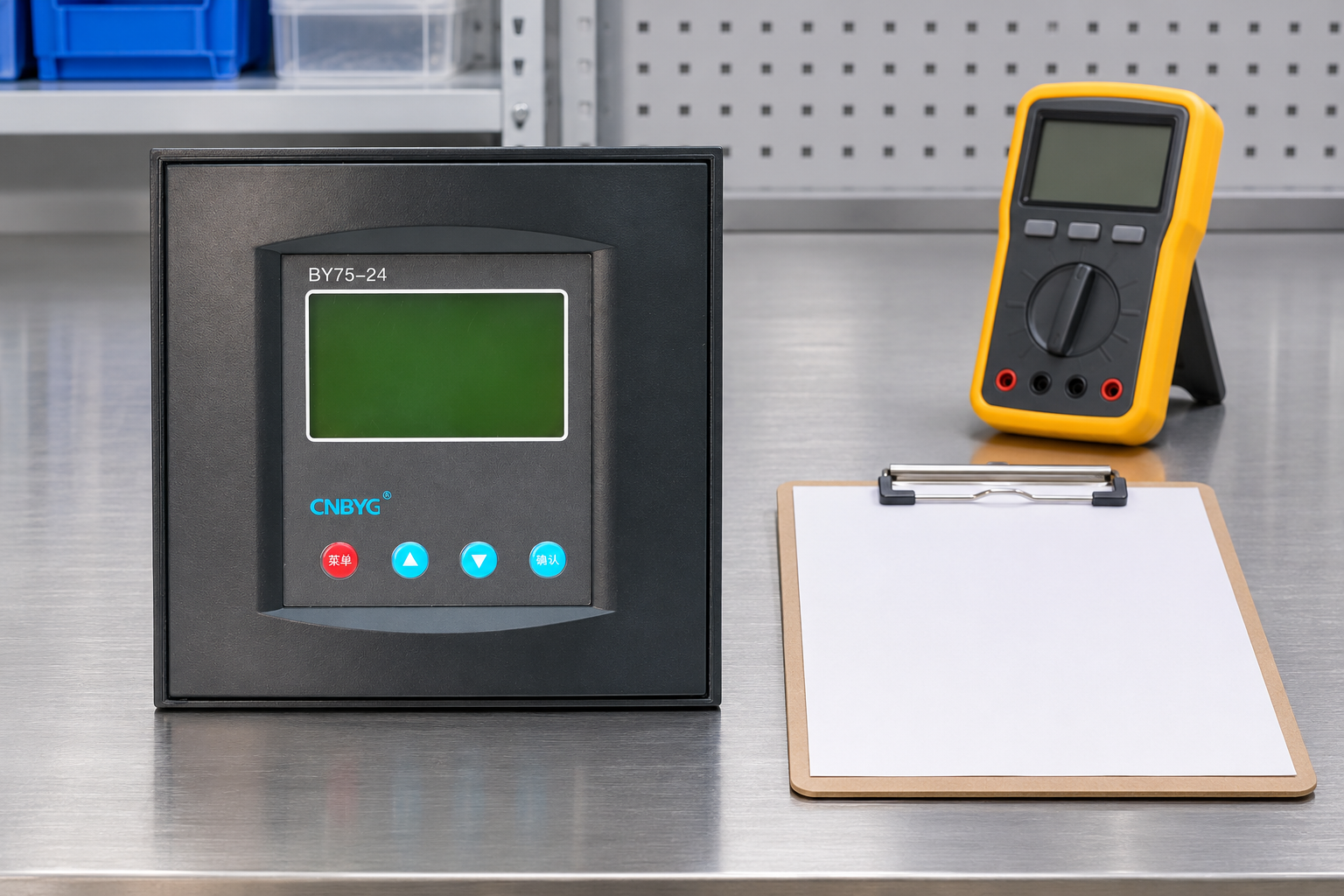
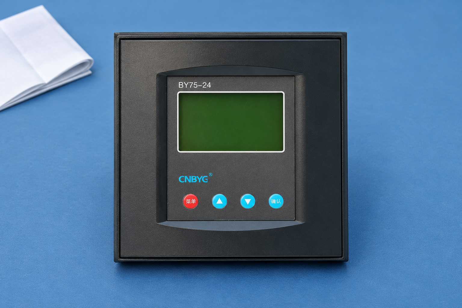
CNBYG’s BY75 reactive power compensation controller is relevant to the controller selection and documentation review. Confirm the exact supplied variant, available inputs and outputs, terminal assignments, output ratings, and power-restoration behavior. This article does not claim that every BY75 variant has a dedicated generator input or an identical menu option. Obtain the delivered manual before specifying the interface.
Review the APFC interlocking and protection logic guide for the broader relationship between commands, permissions, and protective actions. Keep normal operating inhibits separate in the documentation from an isolating device used for maintenance. The two can have very different requirements even when both eventually stop a contactor command.
Treat failure states as part of the design
Ask what happens when a source-status wire breaks, an auxiliary supply fails, an interposing relay becomes defective, or two source indications disagree. The required behavior should be designed and tested rather than discovered during a real outage. Do not assume that an open or closed contact automatically represents a fail-safe arrangement without examining the whole power and control path.
Include the possibility that a contactor fails to reach its commanded state. Define the alarm and the permitted next action where the transfer scheme requires confirmation. If the existing installation has no feedback capable of proving the required condition, record that limitation and obtain an engineering decision. Adding a confirmation contact or modifying a transfer permissive changes the control design and must be assessed as such.
Keep discharge requirements in the restoration sequence
After a stage disconnects, its capacitor charge does not disappear instantly. The return-to-service sequence must respect the installed discharge arrangement and approved reconnection conditions. A transfer event does not waive those requirements. Likewise, the time for a source to stabilize and the time required before capacitor reconnection describe different conditions; one convenient timer should not silently substitute for both.
Do not use a generic delay from another bank or infer a residual voltage from elapsed time alone when a different verification is required. Record the exact component instruction and approved sequence reference. After utility restoration, confirm that measurements correspond to the restored bus arrangement before automatic stages rejoin service. CT location, source topology, and any bus-tie arrangement must remain consistent with the controller’s intended measurement boundary.
Plan functional tests without creating an uncontrolled transfer
Start with a documented test plan identifying personnel, the work boundary, test facilities, expected outputs, and interruption constraints. Test isolated control functions or simulations only where the approved procedure permits them. State precisely what a simulated source indication covers and which physical transfer actions it does not exercise. An input simulation alone is not a complete operational transfer test.
OSHA 1910.333 distinguishes electrical isolation and work practices from ordinary control functions. Apply the governing requirements for the site. Multiple sources and stored capacitor energy must be addressed before work on the control or power circuits. Do not bypass an interlock to run a test outside the approved operating sequence, and do not open an energized CT secondary as a diagnostic shortcut.
Observe the final stage response
For each approved test case, record the source-state evidence, transfer request, inhibit state, controller output, and final switching-device observation. Identify the time basis used for each record. A controller history and a transfer-switch event log may not share the same clock, so an apparent order in separate exports needs validation before being interpreted as proof of sequencing.
Where the plan includes an actual operational transfer, confirm the required bank behavior before, during, and after the change. Include the lowest expected generator load within the approved test scope, because the reactive balance may differ substantially from a heavily loaded utility-fed condition. Do not intentionally create a prohibited leading-load condition merely to demonstrate that protection will respond. Record the cases that remain untested and the restrictions on release.
Verify measurement and settings after restoration
Return the controller to its approved mode and compare settings with the pre-test record. Confirm that no temporary force, bypass, disconnected input, or altered setpoint remains. Check the intended utility PF target and stage delays against the accepted settings, using the controller commissioning settings guide for the broader setup task after verifying its applicability to the installed controller.
Store the accepted cause-and-effect table, test records, updated drawing, generator approval, and unresolved limitations together. The record should allow a later technician to identify why a stage is inhibited on generator power without defeating the interface. Revisit this review when the transfer arrangement, generator, essential-load list, capacitor stage capacity, or controller hardware changes.
Educational background: source transfer
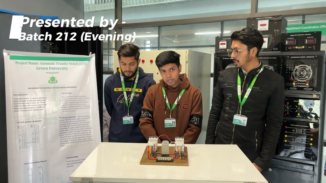
Green University’s electrical engineering department presents an educational automatic-transfer-switch project. It illustrates the distinction between source availability and the act of selecting a source. It is a student laboratory demonstration, not an industrial APFC interlock design or a wiring procedure to copy into a live panel. The project’s simplified arrangement does not establish the required sequence for the installation described above.
Frequently asked questions
Does generator running mean the bank must already be enabled?
No. A running generator may not yet supply the bus, and generator operation does not itself authorize capacitor operation. Define bank permission from the approved source state and compensation operating requirements.
Can switching the APFC controller OFF prove every stage is open?
Not by itself. Identify the actual command paths and final switching elements, including fixed capacitors and manual controls. Use the confirmation required by the approved design rather than assuming a front-panel indication proves the whole power circuit.
Is one standard reconnection delay suitable for every transfer?
No. The sequence must account for the installed capacitor discharge requirements, source stabilization, transfer completion, and valid measurement conditions. Obtain the applicable component and system instructions before defining the delay.
Can the bank operate on generator power after a special review?
That is a system engineering decision requiring the generator’s reactive capability, connected loads, compensation behavior, switching sequence, and protection to be assessed together. Do not carry utility-mode settings onto generator operation without explicit design approval.