Capacitor Bank Infrared Inspection: Planning and Reporting
A capacitor-bank infrared inspection is a planned thermal survey that helps locate unusual heating while documenting the bank’s operating state. A useful report includes equipment identity, active stages, load conditions, ambient conditions, camera settings, visible-light references and the basis for comparing temperatures. A colorful image alone cannot prove a loose connection, a failed capacitor or a healthy bank. The survey must be performed by qualified personnel using an approved electrical-safety procedure, with findings assessed against the actual equipment and followed by appropriate investigation.
Define the question before taking images
Decide whether the survey is a baseline, a periodic condition check, an investigation after an alarm or verification after a repair. These purposes require different comparisons. A first survey can establish a reference under documented conditions, but it cannot demonstrate an improvement without a comparable earlier record. A post-repair image taken at a much lower load may not answer whether the original problem has been corrected.
Identify the bank, stage arrangement and components to be assessed. The plan may include accessible connection areas, switching devices, reactors, capacitor surfaces and ventilation-related observations, but the actual route depends on safe access and the approved method. Do not treat an article’s component list as authorization to open a live enclosure or approach exposed parts.
The US Department of Energy operations and maintenance guide describes infrared thermography as a predictive-maintenance technique and discusses abnormal heating associated with electrical connection problems. The practical lesson is to treat thermal observations as evidence for condition assessment, rather than an automatic diagnosis from a color palette.
Record which stages are actually operating
A capacitor bank changes configuration as its controller switches stages. If one stage is off and another is carrying current, their surface temperatures do not form a like-for-like comparison. Record the stage status and operating history associated with each image. Where the approved survey includes electrical loading information, preserve that information with the thermal record rather than in an unrelated notebook.
A recently energized stage and a stage that has operated for a sustained period may also be at different thermal conditions. Ask the survey specialist to define the observation method and limitations. Do not invent a universal waiting time that applies to every enclosure, reactor and load profile. The report should state what operating state was observed and why it was appropriate for the intended comparison.
This distinction is particularly important when investigating light-load behavior or frequent stage changes. A short snapshot can miss an intermittent condition. Use the operating log to decide whether an additional survey under another relevant state is needed, rather than repeatedly imaging the same low-information condition.
Compare like components under comparable conditions
Useful comparisons can include equivalent phase positions, matching stages under similar duty or the same component across surveys. Each comparison needs context. Different stage capacities, component constructions, airflow paths or enclosure locations can produce different temperatures without establishing a defect.
Keep the visible-light image or another clear position reference with each thermogram. A close thermal image that cannot be located later makes repair planning difficult. Identify the component, phase or terminal position using the equipment’s established drawing and labels, without reaching into the equipment to add a marker during the survey.
A qualified reviewer should distinguish a suspicious pattern from a final root-cause conclusion. For example, a connection area that appears warmer may warrant investigation, but the image alone does not establish torque, contact condition or conductor damage. Any follow-up electrical or mechanical inspection must use an approved procedure and the manufacturer’s instructions.
Account for emissivity and reflected radiation
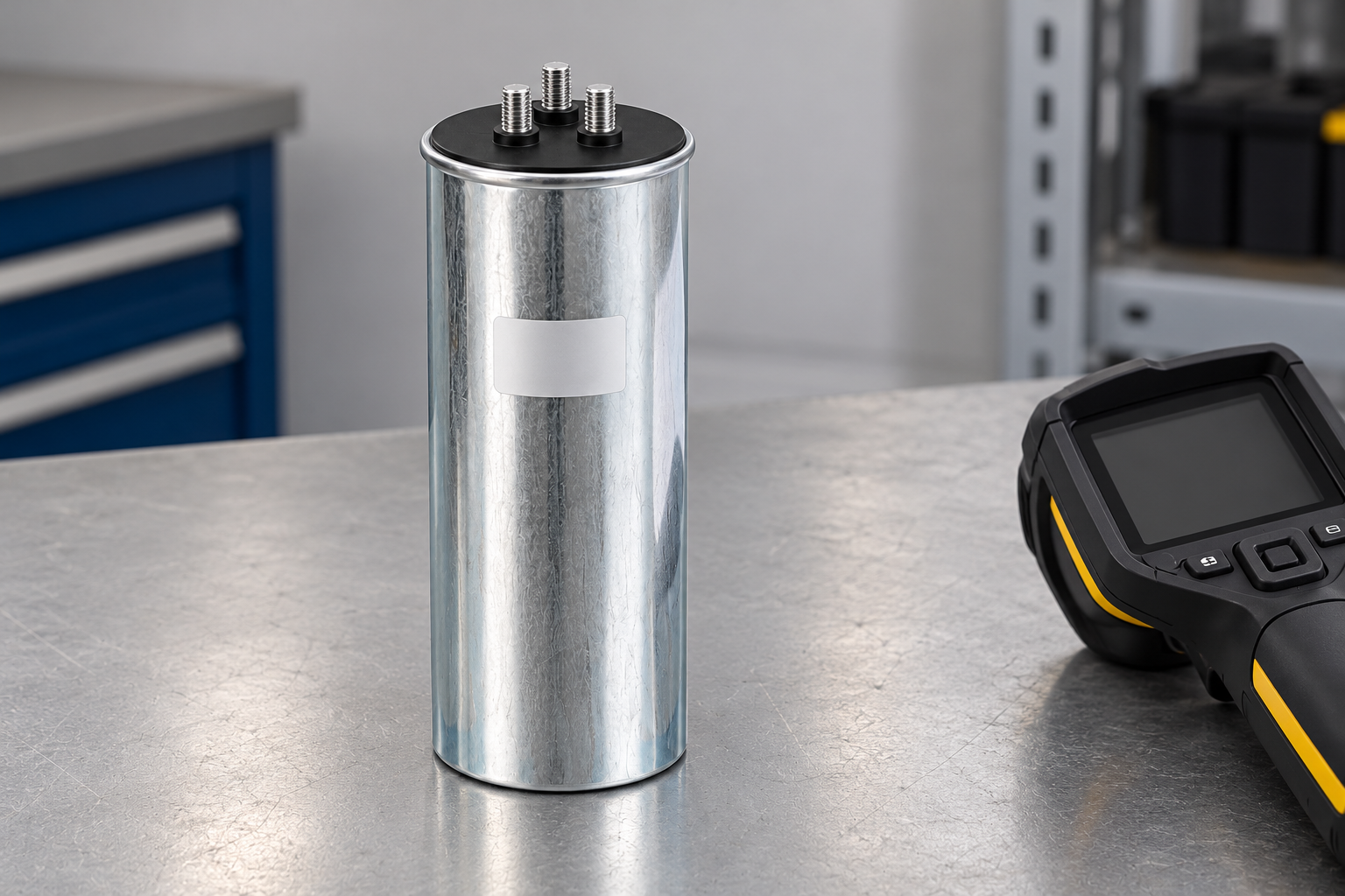
An infrared camera responds to radiation reaching its detector. Converting that signal into a surface-temperature estimate requires assumptions and suitable settings. The NIST resource on infrared spectral emittance explains the importance of emissivity in radiation measurement. This is one reason why shiny metal surfaces require careful interpretation rather than a default assumption that every displayed number is equally reliable.
A bright or reflective capacitor can may reflect its surroundings. Camera angle, nearby heat sources and differences in surface finish can affect what appears in the image. A visible hot area therefore needs assessment of whether it represents the component surface or a reflected source. Do not paint, tape or otherwise modify energized equipment to improve a reading without an approved equipment-specific method.
The specialist should record relevant settings, viewing conditions and limitations. Where a surface cannot be measured reliably by the selected method, state that limitation and choose a suitable alternative through the responsible team. Suppressing uncertainty to create a neat report makes future comparisons less trustworthy.
Use a report structure that supports a decision
A practical report separates observations, interpretation and recommended action. The observation records what was seen under which conditions. The interpretation describes why the pattern warrants attention and what uncertainty remains. The action identifies the investigation or follow-up needed, with responsibility and timing assigned through the site’s maintenance process.
| Report field | What to record | Why it matters |
|---|---|---|
| Equipment identity | Bank, stage and component location | Allows the finding to be located again |
| Operating state | Active stages, relevant loading and duration context | Prevents comparisons between unlike duties |
| Environment | Ambient and enclosure-related conditions | Helps explain changes between surveys |
| Measurement method | Camera, settings, view and relevant limitations | Supports repeatability and uncertainty review |
| Comparison basis | Similar phase, matching stage or earlier baseline | Makes the temperature difference interpretable |
| Disposition | Investigation, responsible person and follow-up evidence | Turns an image into a maintenance decision |
The table supplies qualitative reporting requirements. It does not assign a universal temperature alarm or a severity threshold to CNBYG equipment. Such limits must be appropriate to the component, approved maintenance method and actual operating conditions.
Keep capacitor and reactor findings distinct
A detuned bank contains components with different thermal behavior. A reactor and a capacitor should not be judged by the same surface-temperature expectation merely because they occupy the same cabinet. Compare each with its applicable documentation and equivalent duty, while considering how the bank’s ventilation arrangement affects the whole assembly.
The CNBYG BSMJ cylindrical capacitor page provides capacitor-family conditions and use instructions. The CKSG reactor page separately describes reactor environmental conditions and thermal protection. Neither product illustration supplies a universal thermography acceptance temperature.
If the survey suggests abnormal reactor heating, retain current and operating-state evidence for the responsible engineer. Read detuned reactor temperature rise and protection for that separate diagnostic topic. A thermal trip, unusual surface pattern and a high room temperature can be related, but they are not interchangeable explanations.
Investigate without turning a survey into live repair
An infrared survey can identify a reason for maintenance, but it is not an instruction to tighten hardware, move conductors or replace parts while energized. The safe response depends on the severity assessment and the site’s approved electrical procedures. If the condition requires immediate action, the qualified responsible team must determine that action using the actual installation information.
A capacitor bank can retain hazardous energy after isolation. UC Berkeley’s energy-isolation program explicitly includes equipment with stored energy, including capacitors, in its planning. Follow the actual site’s rules and manufacturer’s instructions for any subsequent access or testing. A dark display or an open switching device is not proof of a safe condition.
Keep the original thermograms and accompanying data after the work. Replacing a component without retaining the reason for replacement makes it difficult to determine whether the cause was addressed. When a connection issue is suspected, preserve the relevant findings from the approved deenergized inspection and the manufacturer’s disposition.
Verify the result under a meaningful comparison
After corrective work, define what evidence will show that the finding has been resolved. A follow-up survey should document comparable operation where practical and disclose differences that affect interpretation. Do not label a repair successful solely because the new image uses a cooler color scale or was taken with a stage switched off.
The capacitor-bank maintenance checklist provides the broader maintenance workflow. Thermography contributes one kind of evidence within that workflow; it does not replace visual inspection, electrical checks, protection review or the manufacturer’s required maintenance.
Build a trend record that future staff can understand. Preserve the date, equipment changes, load context, measurement settings and the outcome of investigations. A sequence of comparable observations can be more useful than a large collection of isolated images with no explanation of what changed.
For the assembly context behind the inspection route, see what capacitor banks contain and how they operate. Identify the actual arrangement before comparing components.
Further learning
Watch the capacitive-reactance lesson
The NPTEL lecture introduces infrared-thermography principles. It explains the measurement background rather than providing permission for live inspection or a capacitor-bank temperature limit.
Frequently asked questions
Can a thermal image prove that a connection is loose?
No. It can identify a suspicious heating pattern that requires qualified investigation. The image alone does not establish torque, contact condition or the final cause.
Why must the active capacitor stages be recorded?
An off stage and an operating stage have different duties. Their temperatures cannot be compared as if they were equivalent observations.
Is a shiny capacitor can easy to measure accurately?
Not necessarily. Emissivity, reflections and viewing conditions can affect apparent temperature. A qualified thermographer must assess the method and disclose limitations.
Does a normal survey mean the bank needs no other maintenance?
No. Thermography is one condition-assessment method. It does not replace the other inspections and checks required by the equipment and maintenance plan.