Power Capacitor Terminal Torque: Joint Preparation and Verification
Power capacitor terminal tightening torque must come from the exact capacitor and connector documentation. There is no safe universal value for every terminal with the same apparent thread diameter. The terminal construction, conductor or lug, hardware stack, surface condition and permitted assembly method all matter. Before assembly, obtain the approved value with units and distinguish the electrical terminal from any case mounting stud. Never copy a cabinet bolt torque onto a capacitor terminal or increase torque to compensate for a damaged joint.
For panel builders, the useful result is a repeatable connection process and an auditable assembly record. This guide covers documentation, joint preparation and verification. It does not supply an unverified CNBYG torque setting or a procedure for work on energized equipment.
Identify the exact connection before looking up a value
Start with the capacitor model, terminal variant and production documentation. A catalogue photograph can establish the product class, but it cannot establish the permissible mechanical load on an individual terminal. A replacement with the same kvar and voltage can have a different terminal construction.
The CNBYG BSMJ cylindrical capacitor family provides the relevant product context for this article. Obtain the terminal drawing and installation instructions for the ordered model. Ask the supplier to identify the torque applicable to the electrical connection, any counter-holding requirement and the separate mounting arrangement.
Keep the lug and conductor documentation alongside the capacitor instructions. The complete joint must be compatible: a mechanically suitable thread does not establish that a lug accepts the conductor material, cross-section or number of conductors. If two documents appear to require conflicting assembly conditions, seek an approved clarification rather than selecting a compromise value.
Understand what tightening torque controls
Tightening a threaded connection creates a clamping load through friction and deformation in the joint. The relationship between applied torque and resulting preload depends on more than thread size. Surface finish, lubrication, hardware geometry and assembly condition can change the result.
NASA’s Fastener Design Manual explains general fastener torque, friction and joint-design considerations. It provides useful mechanical background, not a table of approved torque values for power capacitor terminals. Applying an unrelated structural-bolt value to a capacitor can damage the terminal assembly or its insulation.
Too little effective clamping can contribute to an unstable connection. Too much can strip threads, damage a terminal, distort a connector or transmit force into the capacitor structure. Neither risk is resolved by tightening until a connection feels secure. A documented assembly method is more useful than an operator’s memory of how another product behaved.
Separate terminal torque from mounting torque
A cylindrical capacitor can have electrical connection hardware at the top and a different mounting arrangement at the base. These locations serve different purposes and can have different limits. A statement such as “capacitor torque” without identifying the location is incomplete.
Prepare a drawing or assembly sheet that clearly identifies each controlled connection. Include the approved hardware sequence, conductor termination and any required support. Do not assume that a washer or nut supplied for mounting is interchangeable with electrical terminal hardware.
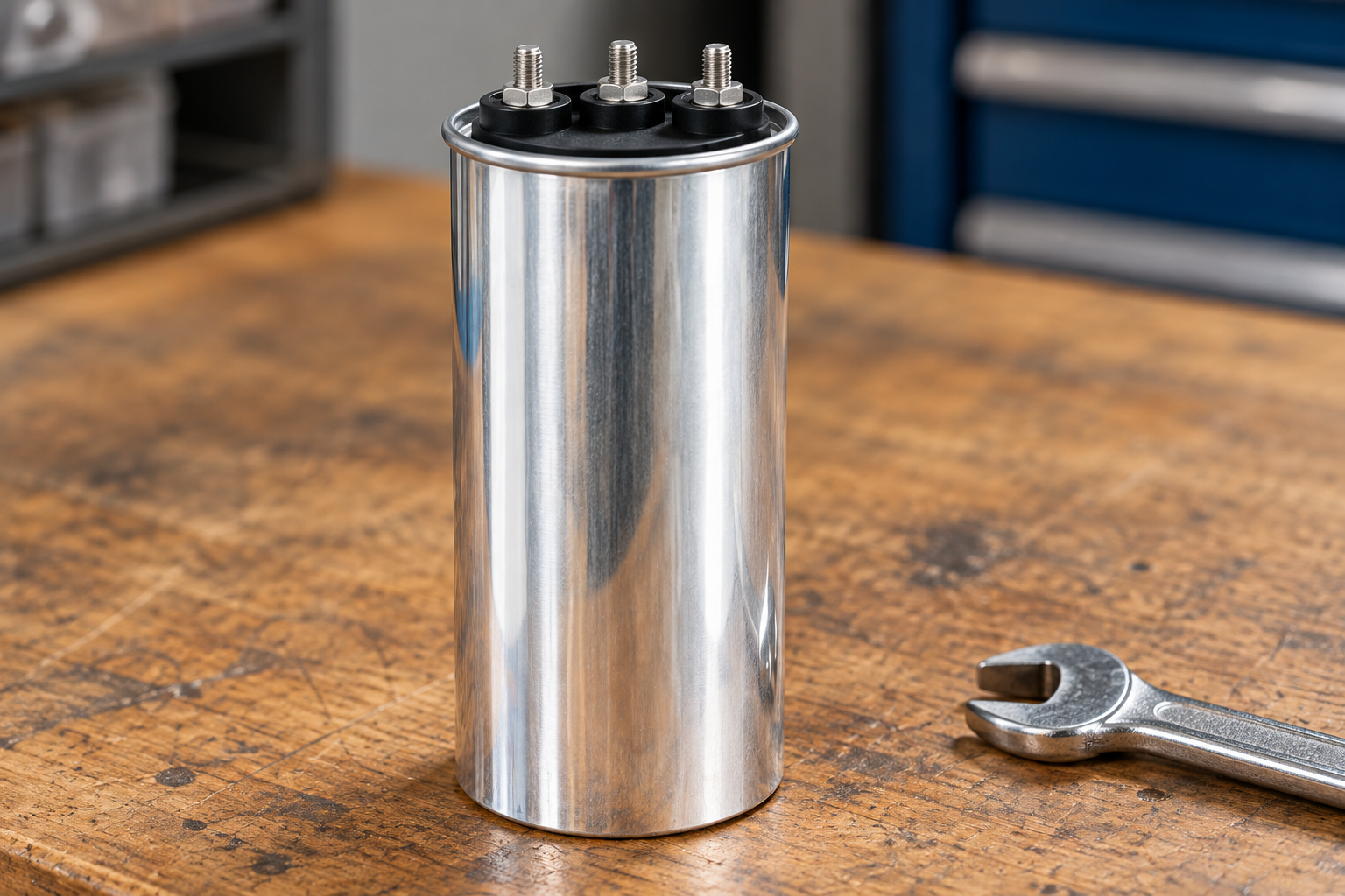
Where the manufacturer requires counter-holding, follow that model-specific instruction. Applying twisting force through the terminal or capacitor top can create damage that is not obvious from an external inspection. This article does not infer a counter-holding method from the reference photograph; the manufacturer must define it.
Mounting also needs to preserve the clearances and movement required by the capacitor design, including any protective disconnector arrangement. A mechanically tight assembly can still be unsuitable if a bracket or conductor prevents the intended protective operation. Review the complete installation rather than treating torque as an isolated number.
Prepare the joint using the approved materials
Use the specified conductor termination, hardware and contact preparation. Verify conductor material and lug suitability before assembly. Improvised substitutions can change both the electrical contact and mechanical behavior.
Do not add oil, grease, thread compound or abrasive treatment unless the approved instructions call for it. Lubrication can change the torque-to-preload relationship, while inappropriate surface treatment can remove protective finishes or introduce contamination. An apparently helpful workshop practice can invalidate the documented assembly condition.
Inspect for damaged threads, distorted lugs, cracked insulating parts, contamination and evidence of previous overheating. Reject or quarantine questionable components for the responsible engineer’s review. Tightening harder is not an acceptable repair for a stripped thread or a burned contact surface.
Route and support conductors so that their weight, bending force and movement do not load the capacitor terminal unnecessarily. The correct tightening value does not compensate for a conductor pulling a terminal sideways. Confirm the approved conductor arrangement before the final joint is made.
Create a practical torque-control record
| Record item | What should be written down | Error it helps prevent |
|---|---|---|
| Product identity | Capacitor model, terminal variant and drawing revision | Using a value from a superficially similar capacitor |
| Connection location | Electrical terminal, mounting stud or another joint | Applying one torque to every threaded part |
| Approved assembly | Lug, conductor, hardware order and surface condition | Changing friction or contact geometry without approval |
| Torque requirement | Value, unit, source and permitted method | Confusing N·m with another unit or relying on memory |
| Tool status | Tool identifier, suitable range and calibration status | Using an unsuitable or uncontrolled tool |
| Completion evidence | Operator, date, inspected joint and exceptions | Losing traceability when a later hot joint is investigated |
This is a documentation framework, not a replacement for the ordered model’s instructions. Where the torque or assembly method is missing, retain a hold point until the supplier or responsible engineer resolves it. Do not populate the blank with a general internet chart.
Choose a tool appropriate to the specified range
The tool must be capable of applying the documented torque with the required control. Check its range, condition, calibration status and operating instructions. A large wrench used near the bottom of an unsuitable range can make a small terminal connection difficult to control.
Adapters and extensions can affect the applied torque depending on their geometry and the method used. Follow the tool manufacturer’s instructions and the approved assembly procedure. Do not make an undocumented adjustment by guesswork or use the tool to loosen a joint unless it is designed for that operation.
Operators should understand the tool’s indication and the required stopping action. Repeatedly clicking a wrench on the same joint or adding an extra pull “for certainty” is not a universal verification method. Record the specified completion method and train the people performing it.
The introductory torque lesson later in this article explains the physical quantity and lever arm. It does not turn a force calculation into an approved capacitor terminal value. The component’s mechanical limits remain decisive.
Verify the assembly without creating new damage
Verification should check the approved hardware, conductor seating, insulation condition, support and recorded assembly process. A paint witness mark can help identify later movement, but it does not independently prove that the correct torque was originally applied.
Do not assume that measuring breakaway torque after assembly reproduces the original tightening torque. Friction, settling and the direction of movement can affect the result. The responsible quality plan should specify any audit method and its acceptance criteria instead of treating every available torque reading as equivalent.
If an error is found, follow the approved rework procedure. Some hardware may require replacement, and some damaged terminals may make the capacitor unsuitable for use. Record the disposition rather than hiding a rejected joint behind a fresh witness mark.
For operational follow-up, capacitor bank infrared inspection can help identify abnormal thermal patterns under an appropriate work method. A thermal image is supplementary condition evidence; it does not replace documented assembly or establish that every internal connection is correct.

Keep maintenance rules model-specific
Routine retightening is not a universal requirement. Follow the capacitor and connector manufacturer’s maintenance instructions and the site’s engineering plan. Unnecessary disturbance can damage hardware or change a previously acceptable joint.
When abnormal heating is found, investigate load, harmonic current, conductor condition, contact damage, ventilation and the assembly record together. See capacitor bank overheating causes for the broader diagnostic context and the maintenance checklist for record planning. Do not assume every warm terminal needs a higher torque.
All inspection or rework involving exposed electrical parts must follow the site’s isolation, discharge and verification requirements. The UK HSE electrical safety guidance provides general workplace safety context. A disconnected supply does not by itself establish that a capacitor contains no stored energy.
What to request with a capacitor order
Ask for the exact terminal drawing, conductor and lug compatibility, hardware supply scope, approved torque with units, mounting requirements and maintenance instructions. Include the planned conductor size and cabinet arrangement so that incompatibilities can be resolved before production.
Keep the response with the purchase and assembly records. If a supplier changes the terminal design or hardware, require confirmation of the applicable instructions before using the previous process. A stable record helps panel builders make consistent joints and investigate problems without inventing a specification after the fact.
Further learning: what torque means
Khan Academy’s introductory lesson explains torque and the effect of a lever arm. It supports the mechanics behind controlled tightening, while the actual capacitor joint requirements remain model-specific.

Frequently asked questions
Can I use a general bolt chart for a capacitor terminal?
No. A general chart does not establish the mechanical limit or approved assembly condition of the capacitor terminal. Obtain the exact product instructions.
Is mounting-stud torque the same as electrical-terminal torque?
Not necessarily. Identify each connection and use its own documented requirement. Similar-looking threaded parts can serve different purposes.
Does a witness mark prove the joint was tightened correctly?
No. It can provide a visual movement reference, but it does not independently prove the original torque, hardware condition or conductor seating.
Should every capacitor terminal be periodically retightened?
Follow the exact manufacturer’s maintenance instructions and the site plan. Routine retightening without a documented requirement can disturb or damage a connection.