Transient Voltage Monitoring in Industrial Systems
Transient voltage monitoring captures brief changes in the voltage waveform that ordinary trend logs can miss. In an industrial system, begin with the actual failure symptom, select a recorder and input accessories capable of resolving the suspected event, and correlate captured waveforms with switching and equipment records. A normal RMS reading after a trip does not establish that the supply was clean at the moment of failure. Equally, a visible spike does not prove that it caused the trip. Useful monitoring provides timing, location, measurement settings and enough context to test a cause rather than merely collect alarming screenshots.
Define the question before choosing a recorder
Write a narrow investigation statement: which machine stopped, which input was affected, and what observation would distinguish competing explanations? A drive trip during capacitor switching presents a different measurement problem from a controller reset during a thunderstorm. Both may require fast voltage capture, but their trigger strategy, observation period and comparison points can differ. Record the machine operating state and available alarm details before changing any protection settings.
Avoid describing every short disturbance as a transient. RMS voltage events, sustained distortion, communication errors and internal equipment faults may require different evidence. Compare the event terminology with the power quality analyzer selection guide. Keep the initial diagnosis open until measured timing and waveform shape support a classification. A symptom without a waveform is a hypothesis, and an isolated waveform without a symptom is an observation.
What a useful event record contains
Preserve the original waveform rather than only a cropped image. Include the recorder location, voltage connection scheme, channel names, nominal supply, input scaling, trigger condition and clock source. Mark any uncertain information explicitly. If a report identifies channels simply as A, B and C, a later reviewer must still be able to connect them to the installation diagram and understand whether the voltage was measured phase-to-neutral or phase-to-phase.
Record the interval before the trigger as well as the recovery afterward. Pre-event information can distinguish an ongoing disturbance from a newly initiated change. Post-event information shows whether the system returned to its prior state or entered a different operating condition. Neither interval should be chosen solely to make an attractive graph. The investigation question determines what context must remain visible.
Select bandwidth, sampling and input range together
The sample interval alone does not describe a measurement system. The input stage, probe, anti-aliasing arrangement and recorder bandwidth influence the captured waveform. Ask for the complete measurement-chain specification, including the accessories used for the proposed installation. A fast recorder with an unsuitable input accessory cannot recover information removed before the signal reaches the recorder.
As a basic planning calculation, sample spacing equals one divided by sample rate. An illustrative rate of 100,000 samples per second gives spacing of 10 microseconds. That arithmetic is not a recommendation or proof that a particular transient is resolved. A real specification must address the expected event spectrum, measurement bandwidth, signal amplitude, timing and required uncertainty. A waveform occupying only a few samples should be treated cautiously until the acquisition limits are understood.
Input range also matters. Clipped data may identify that the selected range was exceeded, but it cannot establish the true peak. Preserve the clipping flag and repeat with an approved suitable arrangement when necessary. Never adjust probes or voltage connections on an energized circuit simply to improve a trace. Connection, isolation and reconfiguration belong to qualified personnel following the applicable site procedure.
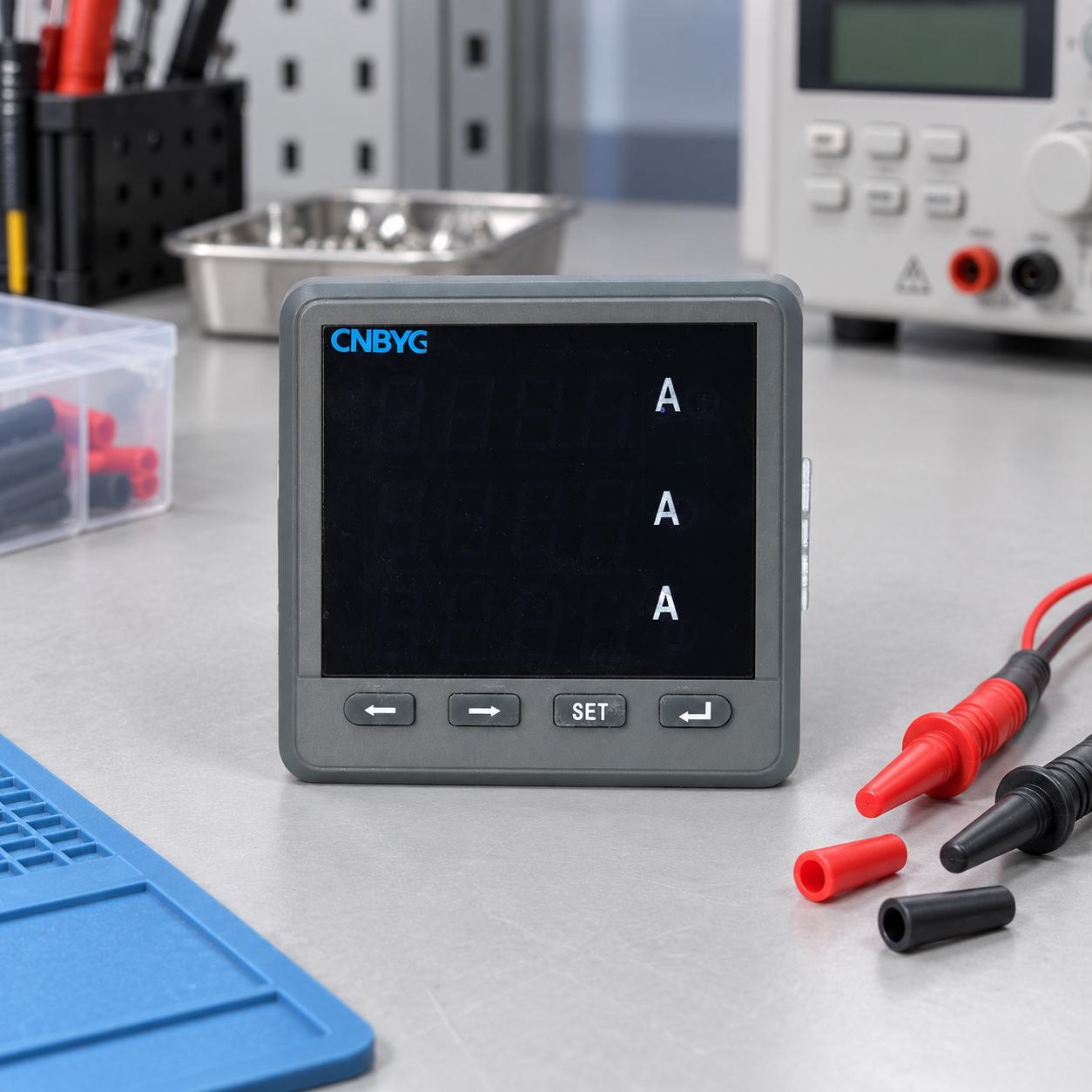
The pictured BY194 is a product-reference illustration of an ordinary panel instrument. It is not evidence of transient recording bandwidth, oscilloscope functions or a certified power quality class. Verify the exact model documentation before assigning any measurement task.
Build a practical acquisition checklist
The following table is an engineering planning aid, not a table of universal transient limits. Its purpose is to make the evidence usable when the investigation moves from observation to equipment selection.
| Planning item | What to establish | Consequence if omitted |
|---|---|---|
| Investigation point | Supply boundary, affected feeder or equipment input | Event location may be mistaken for event origin |
| Voltage reference | Phase-to-neutral or phase-to-phase connection and scaling | Peak values may be compared on incompatible bases |
| Input chain | Recorder, probes, rated accessories and bandwidth | Displayed waveform may not represent the original event |
| Trigger | Quantity, threshold, hysteresis and record length | Recorder may miss events or fill memory with irrelevant captures |
| Timing | Clock source, timezone and known offset | Switching logs and waveforms may appear falsely aligned |
| Storage | Capacity, overwrite policy and export access | Important events may disappear before review |
| Context | Operating state, alarms and switching activity | Captures may not explain the observed failure |
For measurement-method scope, consult the official IEC 61000-4-30 publication. For instrument functional-test evidence, consult IEC 62586-2. Use the applicable full documents and project requirements for exact compliance decisions; this checklist is not a substitute for either.
Place instruments to distinguish local and upstream events
A capture at the affected equipment input describes what that equipment encountered. A second synchronized record upstream can help establish whether a similar event was present at a shared supply point. Before interpreting differences, verify connection bases, transducer response and timing. Two instruments using different measurement chains may produce different traces without proving that the feeder created or removed a disturbance.
Select comparison points from a current single-line diagram and the suspected propagation path. Do not install extra recorders indiscriminately. Access restrictions, voltage level and measurement accessories can limit the feasible locations. The power quality meter placement guide provides a complementary location-planning workflow. Record why each point was selected so the eventual conclusion can be checked against the original question.
Choose triggers without losing operating context
Thresholds must suit the signal and the purpose of the investigation. A very sensitive trigger may produce many benign events and hide the relevant records in a crowded archive. A restrictive trigger may capture only the largest event while missing smaller disturbances that coincide with a vulnerable controller state. Start from documented instrument capabilities, then review a short trial period before committing to long monitoring.
Distinguish voltage-level triggers from waveform-deviation triggers and rate-of-change functions. Their names can sound similar while their implementation differs. Obtain a settings export or clear written definition from the recorder documentation. Save the initial configuration, every revision and the reason for revision. Otherwise, a change in event counts may reflect a changed trigger rather than a changed power system.
Correlate events without assuming causation
Compare the waveform timestamp with machine alarms, contactor operations, capacitor-stage changes and known utility activity. Correct for documented clock offsets before comparing sequences. A controller log recorded to the nearest second cannot establish the order of two changes separated by milliseconds. Report that limitation instead of presenting a precise timeline unsupported by the records.
Repeated coincidence is more informative than a single overlap, but it still requires a plausible electrical mechanism. Ask whether the disturbance reaches the affected input, whether the equipment response is consistent, and whether another simultaneous condition could explain the failure. Preserve events that occurred without trips as well as trips without captured events. Those negative comparisons can weaken an attractive but incorrect explanation.
Separate transient protection from harmonic compensation
A short switching-related voltage disturbance is not automatically a harmonic problem. Harmonic compensation, reactive-power control and surge protection address different functions. Before recommending corrective equipment, identify the measured phenomenon and the installation conditions that matter. Do not assume that adding a larger active harmonic filter will remove an event simply because the equipment is part of the same power quality system.
Use the industrial power quality survey to organize the broader investigation. CNBYG BY194 multifunctional instruments may form part of a metering discussion where their documented functions match the task. A separate appropriate transient recorder may still be required. Product selection should follow verified capabilities and measured need.
Illustrative investigation sequence
Consider a hypothetical plant where a drive reports intermittent input alarms near scheduled switching operations. First preserve the drive alarm history and switching schedule. Next plan a safe recording point at the drive supply and, where justified, a comparable upstream point. Review a trial acquisition for scaling, clipping, timestamp alignment and trigger performance before leaving the instruments to collect longer records.
After collection, group events by waveform characteristics and operating conditions. Compare alarmed and non-alarmed periods. If the same disturbance appears upstream, investigate the shared supply path; if it appears only locally, inspect the local installation and confirm the measurement chain before assigning a cause. Any corrective trial should be planned by the responsible engineer, followed by repeat monitoring under comparable operating conditions. This is a workflow example, not a reported CNBYG customer case.
Report the decision, evidence and remaining uncertainty
A useful report contains the original question, installation diagram, instrument configuration, representative and counterexample records, timing limitations and proposed next action. State what the measurements establish and what they leave unresolved. If no matching transient was captured, include monitoring duration, machine operating coverage and capture limits. “No event observed” is more defensible than “no transient exists.”
Retain the raw data and a configuration copy with the report. A supplier reviewing only a picture may not be able to assess input clipping, probe scaling or acquisition settings. Good evidence reduces the risk of buying equipment for the wrong phenomenon and supports a more precise RFQ, including the measurement task that any proposed instrument must demonstrate.
Further learning: standards and monitoring
This neutral NPTEL IIT Delhi lesson explains the wider standards and monitoring context. It supplements the acquisition workflow; it does not establish the capabilities of the meter pictured here.
Watch Power Quality: Standards and Monitoring
Frequently asked questions
Can an ordinary panel meter capture voltage transients?
Only if its exact model documentation specifies suitable acquisition and recording functions for the event. A normal current, voltage or energy display is insufficient evidence. Confirm bandwidth, inputs, trigger behavior, waveform export and record duration before using it for a transient investigation.
Is a higher sample rate always a better choice?
No. Sampling must be considered with input bandwidth, probe performance, range, memory and the investigation question. Extra samples do not restore information removed by the measurement chain, and poorly chosen triggering or storage can still lose the important event.
Does a transient captured during a trip prove the cause?
No. Check clock alignment, electrical location, repeated patterns and counterexamples. Establish that the disturbance reached the relevant input and that the equipment response is plausible. An internal fault or another operating condition may explain the same trip.
How long should transient monitoring continue?
Choose a period that covers the suspected switching and machine operating conditions, with storage and trigger settings that preserve usable records. There is no universal duration. If the relevant operating event never occurs during monitoring, the investigation remains incomplete.