


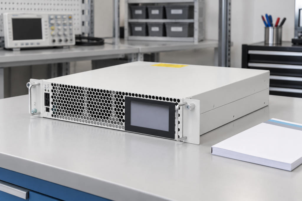
Verifying AHF performance against IEEE 519 requires measurements at the agreed point of common coupling, suitable instruments, representative operating conditions, and evaluation against the applicable standard requirements. It is not enough to show that a filter reduces one feeder’s instantaneous current THD. Define the installation boundary, distinguish current total demand distortion from current THD, retain individual harmonic results, and record voltage distortion alongside current. An AHF is part of a system solution; its catalogue rating or an alarm-free display does not certify the whole installation. This guide organizes the verification record without reproducing or inventing standard limits.
Agree on the acceptance boundary first
Identify the point of common coupling with the responsible utility or project engineer. Mark it on the single-line diagram and record which installation loads and generation sources it represents. A convenient meter at a downstream machine or filter branch is not automatically an equivalent acceptance point.
Clarify the purpose of the test. A commissioning demonstration of reduced source harmonics, a contractual performance test, and a formal assessment against a standard can require different evidence. State the relevant edition of the standard and any applicable project requirements before collecting data. Do not choose an acceptance method retrospectively because it gives the most favorable result.
The IEEE 519 standard information is the primary starting point for the standard’s scope. Use the authorized standard and qualified engineering review for the actual limits and evaluation rules. This article deliberately avoids a universal percentage table because the applicable current criteria depend on the installation and the required assessment.
Keep equipment selection separate from system verification
The CNBYG AHF product page identifies the equipment family used for harmonic compensation. Confirm the installed model, current capability, supported topology, settings, and healthy module count against the approved equipment records.
The separate IEEE 519 and APF sizing guide addresses planning before selection. Here the focus is the measurement and acceptance evidence after installation. A filter selected using reasonable load information can still require commissioning corrections, and a successfully commissioned filter can still face new loads that change the system result.
List other compensation devices and operating arrangements that may influence the test. Include capacitor banks, passive filters, generators, supply transfers, and parallel AHF modules. The final report should explain the configuration being accepted rather than implying that one recording represents every possible plant arrangement.
Understand the current quantities in the report
Current THD uses the fundamental current observed during the measurement as its reference. TDD uses the demand-current reference required by the applicable evaluation. The harmonic numerator and measurement bandwidth also need consistent treatment. Substituting THDi for TDD can produce a misleading conclusion, especially when the plant is lightly loaded.
For a simple arithmetic illustration, suppose the harmonic RMS current is 15 A, the present fundamental current is 50 A, and the agreed demand-current reference is 150 A. The corresponding ratios would be 30 percent THDi and 10 percent TDD under that simplified calculation. These are demonstration values, not measurements from CNBYG equipment or standard acceptance limits.
Document how the demand-current reference was established. Include the data source, period, installation boundary, and responsible approval. Do not choose an unusually large reference simply to reduce the displayed percentage. Where the standard requires particular treatment, follow that requirement and record the basis so another reviewer can reproduce the result.
Prepare an evidence checklist before connecting instruments
| Evidence item | Why it is needed | Record to retain |
|---|---|---|
| Accepted measurement point | Establishes which installation is evaluated | Marked single-line diagram and agreed PCC |
| Applicable standard and requirements | Defines the actual acceptance rules | Edition and project evaluation specification |
| Instrument suitability | Supports confidence in the recorded quantities | Configuration, range, calibration and method |
| Demand-current reference | Distinguishes TDD from instantaneous THD | Source data and calculation basis |
| Individual harmonic results | Prevents total distortion hiding a dominant order | Per-phase harmonic tables and trends |
| Representative operating states | Relates the result to actual plant use | Load, supply and compensation-state log |
| AHF operating evidence | Shows which equipment was available | Module status, settings and event records |
The checklist supports a reproducible engineering assessment. It does not itself certify compliance. Electrical connection and measurement work must be planned by qualified personnel using appropriately rated instruments and the site’s approved safety procedures.
Select instruments for the intended measurement
Confirm that the analyzer measures the required current and voltage quantities, harmonic orders, aggregation intervals, and event information. Check current-probe range, conductor orientation, phase association, and installation topology before recording. A settings error can make a precise instrument produce an irrelevant result.
The IEC 61000-4-30 measurement standard page identifies a reference for power-quality measurement methods. The appropriate instrument capability must be established for the test purpose and requirements. A device with a THD display does not automatically provide the required methods, recording functions, or instrument class.
Retain the configuration file and calibration record where available. Record probe identification and the effective current range. If multiple instruments are used, reconcile their clocks and measurement conventions. Do not combine percentages from instruments using different bandwidths or references as though they were directly comparable.
Record representative plant operation
Define the operating states to include before measurement begins. Consider normal production, major nonlinear loads, lightly loaded periods, and planned supply configurations. The required observation duration and statistical treatment must follow the applicable assessment method rather than a fixed universal number of minutes.
Log load changes and compensation states alongside the electrical recording. A favorable period during which a problematic process is stopped may not represent the plant’s normal use. Likewise, an exceptional event should be identified rather than silently removed or used without context.
Where the project permits a controlled before-and-after comparison, keep the same measurement point and comparable load conditions. Follow an approved commissioning procedure when changing filter state. Some installations cannot tolerate deliberate switching for a demonstration; existing operating intervals or another approved method may be more appropriate.
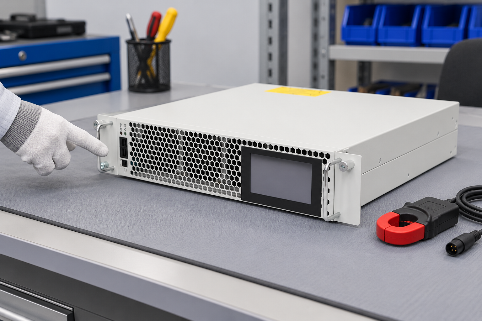

The illustration shows a closed reference product before inspection. It is not a photograph of an acceptance test and does not establish current rating, measurement class, or compliance. The actual verification evidence comes from the documented installation and retained recordings.
Evaluate individual harmonics and voltage results
Retain the per-phase individual harmonic currents and the relevant total measure. A reduced total value can coexist with a remaining significant harmonic order. Review the appropriate criteria for each result instead of reporting only the most favorable number.
Evaluate voltage distortion at the accepted boundary as required. Background supply distortion and network impedance can influence voltage results even when the AHF reduces source harmonic current. Do not attribute every remaining voltage component to filter failure without investigating the broader system.
If the result is unsatisfactory, separate a measurement issue, a sensing or configuration issue, a capacity limit, and an upstream condition. The AHF CT placement guide supports sensing verification. The AHF commissioning guide supports a controlled installation review before further equipment changes.
Interpret a failure without hiding uncertainty
Record which criterion was not met, the affected phases or harmonic orders, and the operating state. Include the measurement confidence and any missing inputs. If the demand-current reference or PCC remains unresolved, state that the assessment is incomplete rather than declaring a pass or fail using a substitute.
Compare compensation demand with available healthy output. Review module status, protective limiting, current allocation, and the load spectrum. A system may require an installation correction, a settings review, additional capacity, or another mitigation approach. The evidence should explain why that action is justified.
After a correction, repeat the relevant test under comparable conditions and preserve the earlier result. Do not replace the original report with a favorable screenshot. A useful record shows the problem, action, and verified effect, including any remaining operating limitations.
Assemble a report another engineer can reproduce
State the site boundary, standard edition, operating configurations, instruments, demand-reference basis, and evaluation method. Attach the relevant harmonic tables and trends, AHF status, settings, event records, and annotated diagram. Separate observed improvement from the formal acceptance conclusion.
Document the responsible reviewer and the unresolved conditions. If the installation later adds drives, changes supply arrangements, or expands compensation equipment, revisit the measurement plan. Acceptance is tied to the configuration and evidence assessed, not a permanent guarantee for every future load.
The NPTEL IIT Delhi lesson below provides additional educational context for standards and monitoring. It does not replace the applicable standard or a qualified assessment of the site.

Watch Power Quality: Standards and Monitoring
Frequently asked questions
Does an AHF with a low THDi display comply with IEEE 519?
That display alone is insufficient. Evaluation requires the accepted system boundary, applicable voltage and current criteria, individual harmonic results, representative conditions, and the required measurement treatment. The filter display may also observe a different point from the PCC.
Can a machine-feeder measurement replace a PCC measurement?
Do not assume equivalence. The feeder may represent only one load and exclude other distortion sources or compensation devices. Agree on the acceptance point with the responsible project or utility engineer and document it on the installation diagram.
Should the test use THDi or TDD?
Use the quantities required by the applicable assessment. THDi and TDD use different current references and answer different questions. Preserve the underlying harmonic currents and document the demand-reference basis rather than substituting one percentage for the other.
What should happen after an unsuccessful test?
Preserve the recordings and identify the specific unmet criterion. Review measurement, sensing, configuration, healthy capacity, and supply conditions before choosing a correction. Repeat the relevant assessment under comparable conditions after the justified change.