Warehouse Conveyor VFD Harmonics: Peak Shift Measurement
Warehouse conveyor harmonic work begins at an agreed feeder boundary, not with a catalog capacity. Capture the meter position, CT reference, and the operating state of the conveyor zones before comparing records. A peak shift can combine induction, merges, sorters, lifts, scanners, and other building loads in a way that a quiet maintenance period does not.
For related planning resources, start with the power quality system guides. This page explains how to make the warehouse record reviewable; it does not promise a system result.
Part 1. Set the feeder boundary before the shift begins
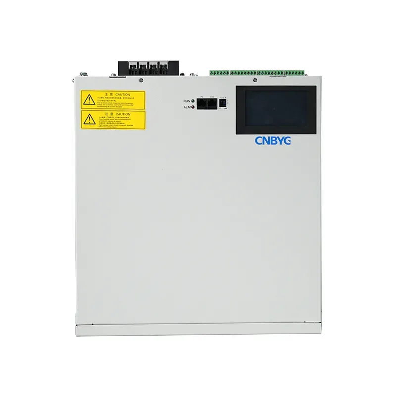
A local record at one VFD answers a local question. A record at the conveyor distribution feeder can show the combined effect of multiple drive groups and coincident loads. Name the decision first: characterize a drive, compare a conveyor feeder, or document an agreed supply-side boundary.
Place the meter and voltage reference on the one-line diagram. Record CT ratio, orientation, aggregation interval, capture duration, and the active load group. These details let a later reviewer distinguish a conveyor-feeder result from a result taken at a single drive input.
Important: Do not use a drive-terminal reading as proof of feeder-level performance. The electrical boundary, operating state, and project acceptance method must be defined together (IEEE 519 overview).
Part 2. Choose peak-shift states worth comparing
At shift change, the important question is which loads were actually coincident. A useful log names the conveyor zones and records whether sortation, lifts, merges, accumulation, charging, HVAC, and other major loads were operating. The aim is comparable operating states, not a large folder of unrelated screenshots.
| Shift-state question | Record with the electrical data | Why it matters |
|---|---|---|
| Which conveyor zones were enabled? | Zone and drive-group identifiers | Different zones can share or leave the feeder. |
| Was induction, sortation, or dispatch at peak? | Time stamp and operating description | The load mix can change during the shift. |
| Did equipment start, stop, or bypass? | Event and speed-change note | A transient is not automatically a steady-state basis. |
| Were other building loads coincident? | Relevant HVAC, charging, or process-load state | The feeder may serve more than the conveyor system. |
The existing conveyor feeder measurement article shows why a feeder needs its own context. A warehouse record should add its own zone and shift information rather than borrowing another site’s operating profile.
Part 3. Capture records that another engineer can review
Reviewable data links voltage and current records to the feeder location and clock. Retain representative intervals with the same meter configuration, then note the load condition beside each interval. The record should show what was measured, where it was measured, and which loads were running.
| Comparison item | Keep constant or disclose | Review use |
|---|---|---|
| Electrical location | Meter point, CT reference, voltage source | Avoids comparing a drive result as a feeder result. |
| Time basis | Interval, duration, and clock reference | Connects the data to a shift event. |
| Load configuration | Running zones and major coincident loads | Separates system behavior from one drive event. |
| Acceptance context | Project metric and responsible reviewer | Keeps a general guide from becoming a compliance verdict. |
The Department of Energy Industrial Technologies Office offers broad industrial-system context. It does not establish a limit or acceptance result for a particular warehouse feeder.
Part 4. Separate conveyor harmonics from other symptoms
Conveyor complaints can involve voltage events, reactive-power demand, controls, mechanical loading, protection, or communications. Do not assume every trip, speed complaint, or voltage observation is a harmonic-filter question. First establish whether harmonic current at the agreed boundary is the problem to be reviewed.
| Observed concern | First question | Do not assume |
|---|---|---|
| Harmonic-current record | Where was it taken and in which shift state? | That one VFD is the only source. |
| Voltage event | Did it align with supply or load switching? | That current mitigation resolves every voltage event. |
| Reactive-power objective | Is reactive behavior the stated target? | That its selection basis matches harmonic-current mitigation. |
| Protective or control alarm | Is there a documented electrical relationship? | That a guide identifies the root cause. |
For a broader evidence checklist, use power quality metering before an APF or SVG RFQ. It is a planning aid, not a substitute for the project review.
Part 5. Review AHF options against the measured scope
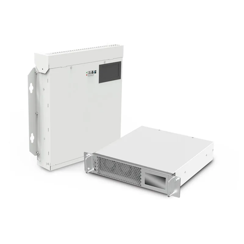
When feeder records identify harmonic current as the agreed objective, an AHF/APF review can be considered. The review still needs a connection point, CT arrangement, load record, protection coordination, room constraints, cooling, cable route, and an acceptance method. The AHF Active Harmonic Filter page is a product-line starting point rather than a warehouse performance promise.
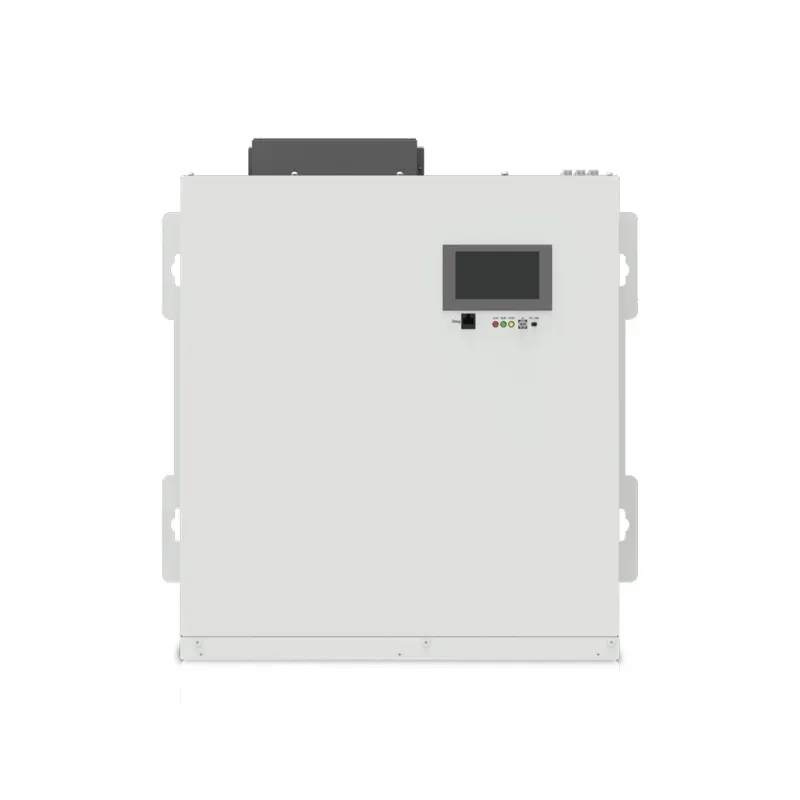
This fit boundary matters. Do not choose equipment from connected motor kW alone, a short capture at one drive, or an undefined throughput objective. A supply-side issue, a reactive-power-only requirement, or a control problem can need a different engineering path.
Part 6. Send a warehouse measurement package with the inquiry
An inquiry becomes more useful when it identifies the electrical boundary and the shift condition. Include the following field set with the request:
| Buyer should provide | Why it matters |
|---|---|
| One-line diagram and nominal system details | Establishes the feeder and supply context. |
| Meter, CT, and voltage-reference positions | Lets the reviewer locate the captured electrical boundary. |
| Representative voltage and current records | Shows the evidence behind the request. |
| Shift log with conveyor-zone state | Connects each record to operation. |
| VFD, conveyor, and other coincident-load inventory | Identifies the relevant load mix. |
| Existing filters, capacitors, and protection details | Identifies integration constraints. |
| Proposed room, cooling, cable, and communications limits | Tests installation feasibility. |
CNBYG can discuss product-line fit for a defined harmonic-current scope. Use the conveyor measurement package to begin that conversation; a general article cannot guarantee a warehouse electrical or operational result.
Frequently asked questions
Where should a warehouse conveyor harmonic meter be placed?
Place it at the electrical location that matches the decision being made, then record that location on the one-line diagram. A drive input and a shared conveyor feeder are different measurement boundaries.
Which conveyor states should be logged?
Log the active conveyor zones, induction or sortation condition, starts and stops, bypass states, and major coincident loads. The purpose is to make electrical records comparable across named shift conditions.
Is a drive-terminal reading the same as a feeder record?
No. A drive-terminal reading describes one local location, while a feeder record can include the combined effect of several connected loads and the supply arrangement.
Can connected motor kW select an AHF or APF?
No. Connected motor kW does not replace a defined harmonic-current objective, feeder location, CT arrangement, operating record, installation scope, or acceptance method.
Does IEEE 519 set a warehouse device size?
No. IEEE 519 provides harmonic-control context, while a project still needs its own electrical boundary, available data, and acceptance criteria.
What belongs in a warehouse conveyor harmonic inquiry?
Send the one-line diagram, nominal system data, meter and CT position, representative records, shift-state log, load inventory, existing equipment, and installation constraints so the discussion has a reviewable scope.