Penyakeliran Titik Gelombang untuk Bank Kapasitor
titik pada saklar gelombang untuk bank kapasitor menutup setiap langkah kapasitor ketika tegangan bus AC cocok dengan tegangan pada terminal kapasitor sehingga perbedaan tegangan seketika—dan lonjakan arus masuk—tetap kecil. Lemari faktor daya otomatis menggunakan waktu sinkronisasi itu sehingga tahap dapat beralih tanpa trip fuse, keausan kontak, dan gangguan bus yang sering dibuat oleh penutupan kontak secara acak.
Panduan ini menjelaskan mekanisme lonjakan arus masuk, kapasitor saklar nol tegangan menggunakan saat sebuah bank dikosongkan, tegangan residu kapasitor setelah pemutusan, penyalaan kembali secara berurutan bahaya pada satu bus, dan bagaimana kontak otomatis dibandingkan dengan saklar campuran dan modul cerdas terintegrasi dalam sebuah bank kapasitor saklar sinkronisasi lemari. Untuk apa sebuah bank dan bagaimana itu cocok dengan koreksi daya reaktif pabrik, mulai dengan artikel terpisah kami tentang apa itu bank kapasitor; halaman ini tidak mengulangi definisi itu atau panduan perhitungan faktor daya apa pun.
Apa arti Penutupan Pada Gelombang untuk Bank Kapasitor
Penutupan pada gelombang—sering disebut penutupan sinkronisasi atau penutupan terkendali—berarti pengendali menutup saklar pada saat yang dihitung di gelombang AC sehingga tegangan di seluruh kontak pembuka sekecil mungkin.
Kapasitor menentang perubahan tegangan mendadak. Jika bus sudah berada pada tegangan seketika tinggi sementara terminal kapasitor masih dekat nol, peristiwa penutupan menerapkan hampir seluruh perbedaan sekaligus. Logika PoW mengukur gelombang langsung, memprediksi di mana tegangan akan berada saat saklar mekanis atau hibrida benar-benar selesai menutup, dan menembakkan perintah lebih awal cukup untuk mendarat di sudut target.
Pada susunan kapasitor yang benar-benar kosong (terdischarge), target yang biasa digunakan adalah penutupan pada tegangan nol. Pada susunan yang baru saja dibuka beberapa saat lalu, targetnya mungkin berupa tegangan puncak atau tingkat menengah sementara muatan meluruh melalui resistor pelepasan atau saat pengendali melacak status sisa.
Insinyur transmisi utilitas menerapkan gagasan yang sama pada pemutus sirkuit tegangan tinggi dengan perangkat switching terkontrol khusus. Kabinet PF otomatis tegangan rendah menerapkannya melalui sakelar majemuk, relai berbantuan tiristor, atau modul kapasitor cerdas terintegrasi. Fisika yang digunakan tetap sama meskipun ukuran perangkat kerasnya berbeda.
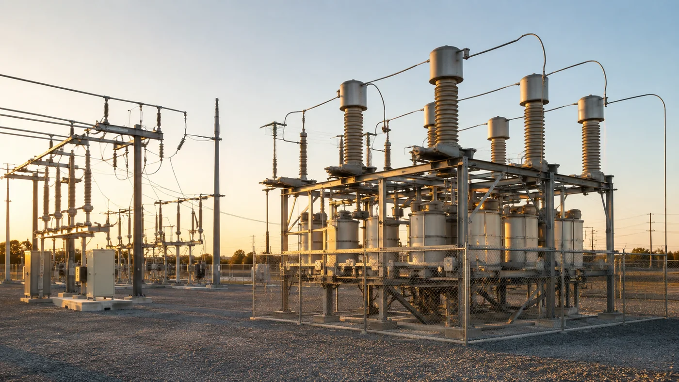
Mengapa Penutupan Bank Kapasitor Membuat Lonjakan Tanpa Kontrol
Arus inrush bank kapasitor muncul karena arus pengisian harus mengalir setiap kali tegangan terminal dipaksa berubah lebih cepat daripada kemampuan kapasitor untuk mengikutinya.
Dalam istilah AC, hubungannya sudah akrab: arus berbanding lurus dengan seberapa cepat tegangan berubah pada kapasitansi. Penutupan kontaktor secara acak oleh karena itu dapat menghasilkan rentang arus puncak yang luas untuk langkah kvar yang sama, tergantung pada posisi gelombang sinus saat kontak bersentuhan.
Beberapa faktor pabrik memperlebar rentang tersebut:
- Impedansi sistem — bus yang kaku dengan impedansi sumber yang rendah memungkinkan puncak transien yang lebih besar.
- Muatan pra-sakelar — kapasitor yang masih menyimpan tegangan dari pembukaan baru-baru ini akan mengalami ΔV yang berbeda dari unit yang sudah dikosongkan.
- Jalur paralel — bank lain yang berenergi pada bus yang sama mengubah jaringan LC yang efektif.
Switching yang tidak terkontrol tidak selalu membawa bencana pada satu langkah tetap kecil yang jarang dibuka. Hal ini menjadi masalah pada kabinet otomatis di mana pengendali dapat menambah atau mengurangi beberapa langkah per jam untuk mengikuti beban motor yang bervariasi.
Kiat: Membuka suatu langkah pada saat arus nol akan membiarkan kapasitor tetap bermuatan. Pengendali yang mencoba menutup kembali terlalu cepat tanpa melacak tegangan sisa kapasitor yang terjebak tersebut masih melakukan switching “acak” meskipun teks pemasaran menyebutkan titik silang nol (zero-cross). — sumber: panduan switching terkontrol utilitas untuk beban kapasitif (kutipan penelitian tentang target muatan sisa)
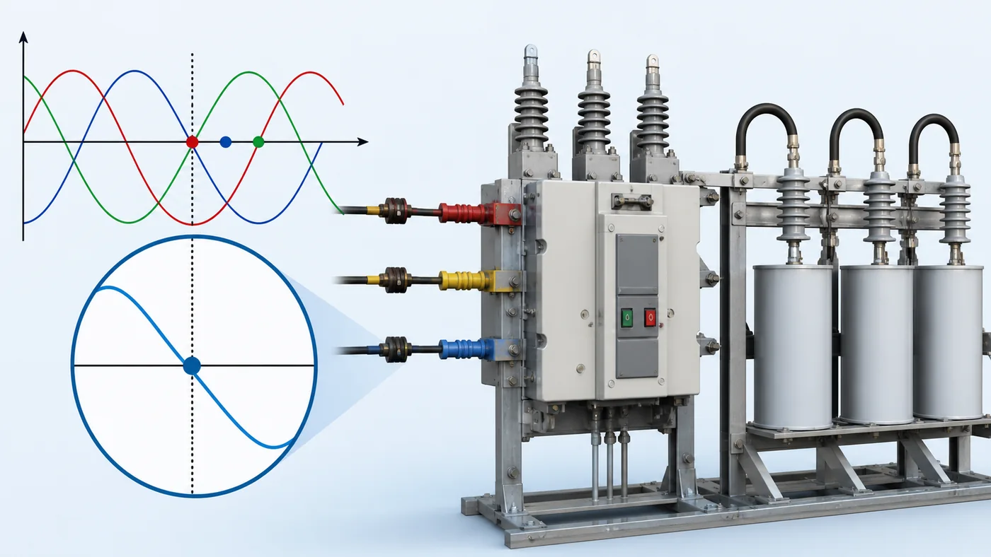
Penutupan Nol Tegangan dan Muatan Residual Setelah Pemutusan
Switching tegangan nol untuk kapasitor adalah kasus khusus di mana bank telah kosong sepenuhnya dan pengendali menargetkan penutupan pada—atau sangat dekat dengan—titik persimpangan nol tegangan sistem.
Pada saat itu, baik terminal bus maupun kapasitor berada di dekat titik nol, sehingga arus pertama terbentuk saat gelombang sinus naik secara alami alih-alih sebagai loncatan. Itulah kondisi ideal yang diiklankan oleh sebagian besar sakelar majemuk LV dan modul kapasitor cerdas.
Kenyataan menambahkan dua kerumitan yang harus diantisipasi oleh pembaca bagian pengadaan:
- Penundaan mekanis dan hibrida — perintah penutupan harus mendahului target sebesar waktu operasional sakelar. Oleh karena itu, pengendali terus-menerus mengukur gelombang dan mengompensasi penyimpangannya.
- Tegangan kapasitor residual setelah terbuka — ketika arus mendekati nol, kapasitor tetap terisi daya mendekati puncak garis sampai resistor pelepasan atau waktu pelurusan menguranginya. Menutup kembali saat muatan masih ada berarti sudut target tidak lagi merupakan penutupan nol-t tegangan. Sistem PoW canggih melacak apakah bank telah dilepaskan, terisi penuh, atau di antara keduanya—seperti yang dijelaskan dalam panduan pengendalian saklar utilitas untuk beban kapasitif.
| Status muatan kapasitor saat penutupan diminta | Target penutupan PoW yang umum | Kesimpulan pembaca |
|---|---|---|
| Dilepaskan sepenuhnya | Persilangan nol tegangan | Meminimalkan ΔV awal |
| Terisi penuh (baru saja dibuka) | Puncak tegangan | Mencocokkan muatan yang terperangkap |
| Dilepaskan sebagian | Intermediate angle on the wave | Controller must track decay, not assume zero volts |
Without that state awareness, a cabinet may still slam steps at the wrong angle while the HMI label says “zero-cross.”
Energisasi kembali secara berurutan pada Bus yang Sama
Back-to-back switching and back-to-back energization both describe closing a capacitor step while another bank or step is already connected on the same bus. The second closure can produce very high inrush even when each step’s nameplate kvar looks modest.
The already-energized capacitors present a low-impedance path. The incoming step sees a stiff voltage source combined with the first bank’s stored energy, which can drive transient currents far above steady-state reactive current. Educational overviews of capacitor switching describe inrush frequencies from hundreds of hertz to a few kilohertz in severe same-bus cases.
Plant scenarios where this shows up:
- A controller adds step 3 while step 2 is still online instead of swapping steps.
- Two independent automatic cabinets share one compensation bus without interlocking.
- Rapid cycling after a brief outage when multiple stages try to return together.
PoW on each individual step helps but does not replace coordination logic. Minimum time between operations, interlocks, and controller algorithms that avoid overlapping closes still matter. CNBYG’s published BYFK composite-switch specification table, for example, lists minimum intervals between turn-on/turn-off and between consecutive connections—parameters buyers should align with controller programming, not ignore.
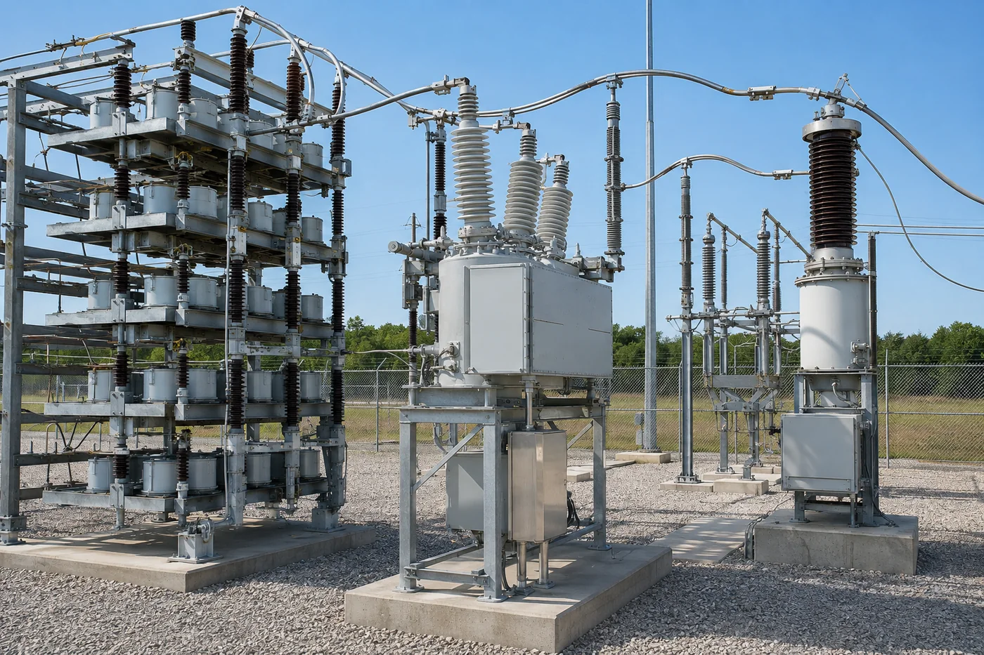
Kontaktor, Saklar Campuran, dan Kontrol Titik pada Gelombang Berbasis Pemutus
Three hardware classes cover most conversations—from LV cabinets to utility substations.
| Approach | How PoW is implemented | Ukuran pas biasa | Awas |
|---|---|---|---|
| Capacitor switching contactor (e.g., dedicated CJ19/GJ19 class) | Often basic timing; may rely on controller pre-contact or auxiliary logic | Cost-sensitive fixed steps with infrequent switching | Random-angle closes still possible if controller does not synchronize |
| Compound / composite switch (semiconductor + magnetic hold relay) | Microprocessor selects turn-on at voltage zero and turn-off at current zero | LV automatic PF cabinets with frequent stepping | Still needs correct residual-voltage logic and minimum intervals |
| HV breaker + controlled switching device (CSD) | Breaker with high repeatability; rate of decrease of dielectric strength (RDDS) and pole-scatter budgets per IEEE application guides | Utility and large MV banks | Not a direct substitute for LV compound-switch specs |
High-voltage application notes stress breaker repeatability on the order of ±0.5 to ±1.0 ms and sufficient rate of decrease of dielectric strength (RDDS) when zero-cross is the target. Those numbers belong to breaker selection on transmission systems, but they explain why “any contactor with a zero-cross label” is not interchangeable with a compound switch engineered for capacitive duty.
At low voltage, the reactive power compensator hub groups controllers, switches, and capacitor steps that are specified together. Switching hardware should be chosen with the controller’s PoW algorithm, not as an orphan part number.
Ketika Penutupan Pada Gelombang Menguntungkan di Lemari Pabrik LV
Point-on-wave switching pays off most when capacitor steps switch often and when inrush would otherwise limit how aggressively the controller can follow load.
Strong fits:
- Multi-step automatic PF cabinets on motor-heavy plants where lagging reactive demand swings across shifts.
- Steps large enough to disturb the bus when closed at a bad angle—nuisance fuse operations, contact pitting, or voltage flicker on sensitive loads.
- Projects where the utility or internal power-quality spec limits switching transients even if steady-state power factor already looks acceptable.
Weaker fits:
- A single fixed capacitor step that rarely disconnects—PoW hardware adds cost with little operational benefit.
- Plants where distorsi harmonisa, cURL Too many subrequests by single Worker invocation. To configure this limit, refer to https://developers.cloudflare.com/workers/wrangler/configuration/#limits.
cURL Too many subrequests by single Worker invocation. To configure this limit, refer to https://developers.cloudflare.com/workers/wrangler/configuration/#limits.
cURL Too many subrequests by single Worker invocation. To configure this limit, refer to https://developers.cloudflare.com/workers/wrangler/configuration/#limits.
Penting: cURL Too many subrequests by single Worker invocation. To configure this limit, refer to https://developers.cloudflare.com/workers/wrangler/configuration/#limits Harmonika IPQDF dan kapasitor faktor daya
Pilih Perangkat Penutupan dan Produk BYFK yang Cocok untuk Langkah Bank Kapasitor
cURL Too many subrequests by single Worker invocation. To configure this limit, refer to https://developers.cloudflare.com/workers/wrangler/configuration/#limits.
cURL Too many subrequests by single Worker invocation. To configure this limit, refer to https://developers.cloudflare.com/workers/wrangler/configuration/#limits cURL Too many subrequests by single Worker invocation. To configure this limit, refer to https://developers.cloudflare.com/workers/wrangler/configuration/#limits cURL Too many subrequests by single Worker invocation. To configure this limit, refer to https://developers.cloudflare.com/workers/wrangler/configuration/#limits cURL Too many subrequests by single Worker invocation. To configure this limit, refer to https://developers.cloudflare.com/workers/wrangler/configuration/#limits.
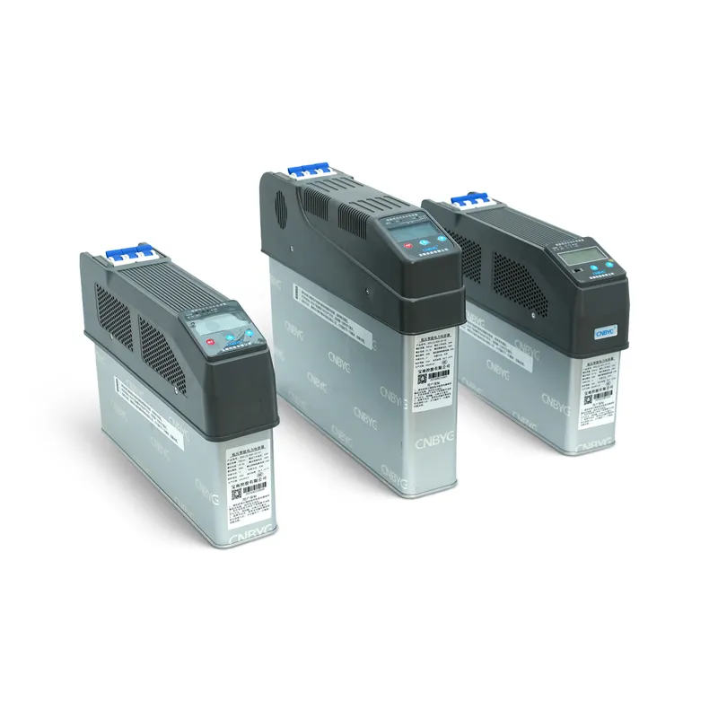
Compound switches cURL Too many subrequests by single Worker invocation. To configure this limit, refer to https://developers.cloudflare.com/workers/wrangler/configuration/#limits BYFK series intelligent low-voltage composite switch target capacitive duty with voltage zero-crossing conduction and current zero-cross cutoff. CNBYG’s published specification table for BYFK lists inrush below 1.5 times rated current, response time under one second, minimum five-second spacing between turn-on and turn-off, and thirty-five seconds between consecutive connections—values that should be checked against your controller’s staging profile.
Integrated intelligent capacitors cURL Too many subrequests by single Worker invocation. To configure this limit, refer to https://developers.cloudflare.com/workers/wrangler/configuration/#limits Kapasitor cerdas seri BY81 embed measurement, control, and synchronous zero-crossing switching inside the module when a distributed step-by-step architecture fits better than a central contactor bank.
Whichever path you take, confirm three items with the supplier and your panel builder:
- Controller and switch share one PoW algorithm including residual-voltage handling.
- Minimum intervals and interlocks prevent back-to-back overlaps your bus cannot absorb.
- Harmonic study precedes energization on VFD-heavy plants—PoW is not a substitute for detuning.
FAQ
What is point on wave switching for capacitor banks?
It is controlled closing (and sometimes opening) synchronized to a target angle on the AC voltage wave so the voltage difference across the switch at contact make is minimized, which limits inrush when the step connects.
Why does switching a capacitor bank cause inrush current?
Capacitors require current whenever terminal voltage changes quickly. Closing at a high instantaneous ΔV forces a large charging current until the capacitor matches the bus.
Is zero voltage switching the same as point on wave?
Zero-voltage switching is the discharged-bank case of point-on-wave control—closing at or near zero volts. PoW also covers closes at peak or intermediate angles when residual charge remains after a previous open.
What is back-to-back capacitor bank switching?
It is energizing a second bank or step while another is already connected on the same bus. The combined network can produce much higher transient current than either step alone.
Does switching off discharge the capacitors immediately?
No. When current is interrupted at zero, capacitors typically retain near-line voltage until discharge resistors or time decay reduces it. The next close must account for that trapped charge.
Do I still need detuning if I use point on wave switching?
Often yes on plants with significant harmonics. PoW reduces energization transients; it does not move resonance points away from characteristic harmonics the way a detuned reactor bank does.
Can low-voltage plants use point on wave switching?
Yes. LV automatic PF cabinets commonly use compound switches or integrated intelligent capacitors with zero-cross control rather than utility-scale breaker CSDs.
How is a compound switch different from a capacitor contactor?
A compound switch uses intelligent timing plus hybrid switching elements to target voltage zero-cross turn-on and current zero-cross turn-off for capacitive duty. A conventional contactor may rely on simpler mechanics unless paired with a controller that truly synchronizes every close.
Referensi
- IEEE Technology Navigator — Capacitor Banks and controlled switching
- E3S Web of Conferences — Diminution of Transient Disturbances for High Voltage Application Integration
- IEEE SA — IEEE C37.012-2022 Guide for Application of Capacitive Current Switching
- Teknologi Kelistrikan — Karakteristik dan Aplikasi Bank Kapasitor
- IPQDF — Harmonics and Power Factor Capacitors: Understanding Failure, Resonance, and the Filter Solution