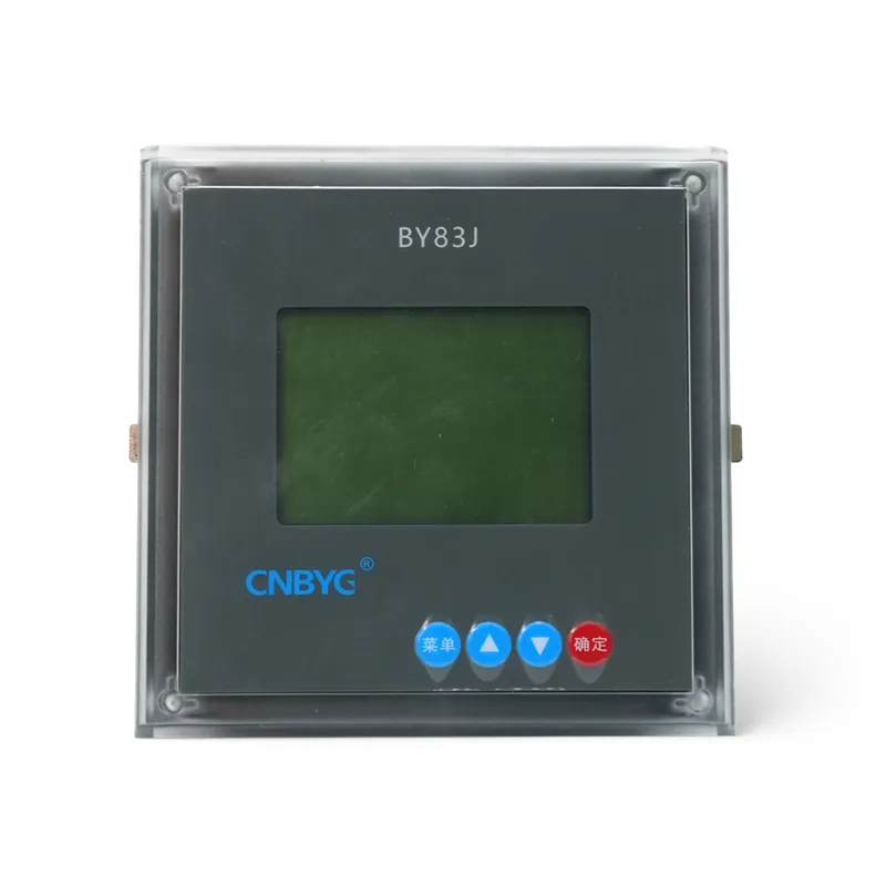

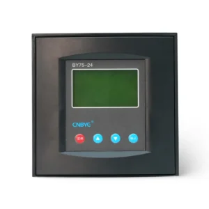
BY83 Series Intelligent Capacitor Controller
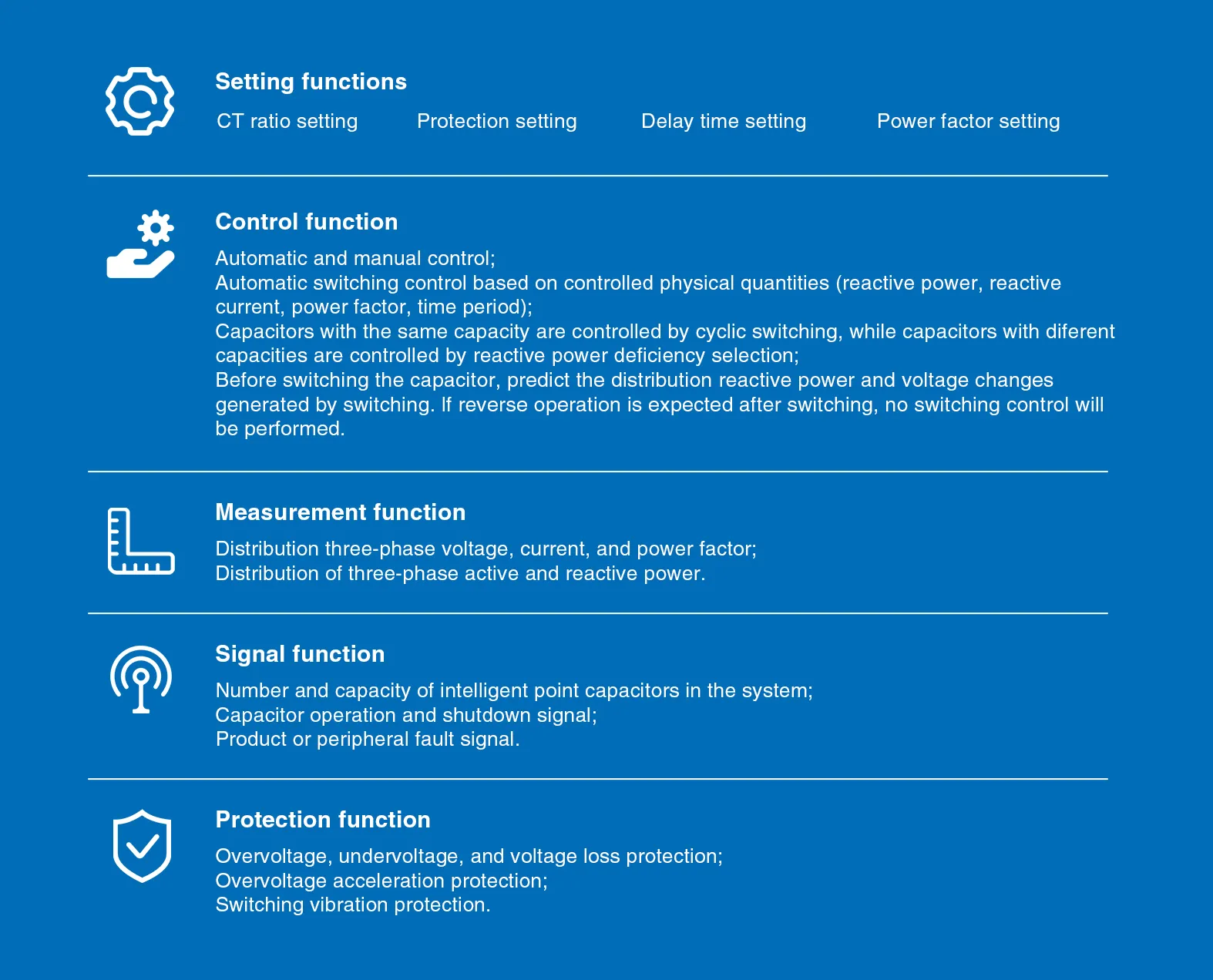
The BY83 series intelligent capacitor controller offers various setting functions, including CT ratio setting, protection setting, delay time setting, and power factor setting. Its control functions support both automatic and manual control, and can automatically switch control based on the controlled physical quantities (such as reactive power, reactive current, power factor, and time period). Capacitors of the same capacity are controlled through cyclic switching, while capacitors of different capacities are controlled based on reactive power selection. Before switching capacitors, the system predicts the reactive power and voltage changes resulting from the switching; if reverse operation is anticipated after the switching, the switching control will not be executed.
Product Description
The BY83 series intelligent capacitor controller has full functionality, flexible installation, Chinese menu display. and convenient operation, It can be used in conjunction with the BY81 series intelligent capacitors, BY82 series harmonic resistant intelligent capacitors, BY86 series controlled intelligent capacitors, andBY89series intelligent capacitors with molded case circuit breakers produced by our company. Using this product can replace the existing low-voltage reactive power compensation cabinet with one vol meter, one voltage measurement conversion switch, one power factor meter, three ammeters, one low-voltage reactive power individual compensation control backup, and all capacitor status indicator lights, making it extremely simple and saving a lot of wiring.
Technical Indicators Of The Product
| Project | Parameter | |
| Work environment | Ambient temperature | -40℃~+55℃ |
| Relative humidity | 20%~90% at 40℃ | |
| Atmospheric pressure | 79.5-106.0kpa | |
| Working power supply | Working voltage | AC 50Hz,380V+20% |
| Function consumption | <30VA | |
| Measurement accuracy | Voltage | Level 0.5 |
| Current | Level 0.5 | |
| Power factor | Level 1.0 | |
| Reactive power | Level 1.0 | |
| Power factor | ±0.01 | |
| Control accuracy | Power factor | ±0.01 |
| Reactive power | +120%of minimum capacitor capacity | |
| Mechanical parameters | Overall dimensions (WxHxD) | 120x120x95mm |
| Opening size (WxH) | 113x113mm | |
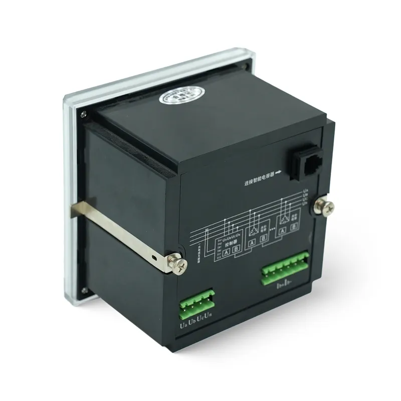
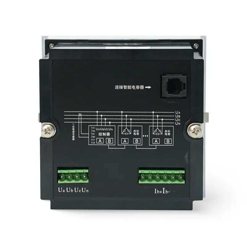
Wiring Diagram
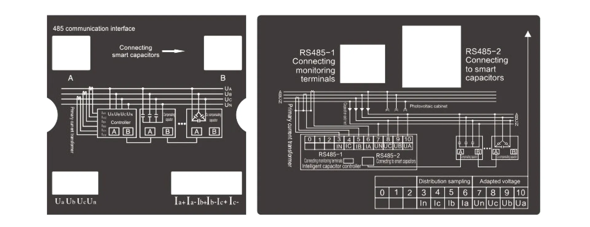
The electrical wiring terminals of the controller are defined as shown in the fiqure:
When in staling the controller, refer to the electrical schematic diagram of the rear panel for wiring
The specific wiring method is:
UA, UB, and UC are connected to A, B, and C three-phase voltages respectively, while UN is connected to the neutralline:
La+, la -, lb+, lb -, Ic+, and Ic -are connected to A, B, and C three-phase currents respectively;
A. B is an RS485 communication interface, which can be connected to the communication port of a low-voltage intelligent capacitor.
Note: When all smart capacitors are co compensating capacitors, only Ib+and Ib – can be connected to the B-phase current line.
Instructions For Using Wiring Terminals
| Project | Parameter | |
| 10㎟ | 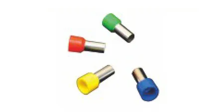 |
For 10㎟ conductor(Single capacitor capacity below 30Kvar) |
| 16㎟ | 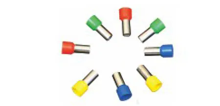 |
For 16㎟ conductor(Single capacitor capacity below 30Kvar) |
Instructions For Using Rs485 Communication Cable
| Specifications | Picture | Purpose |
| 0.5m | 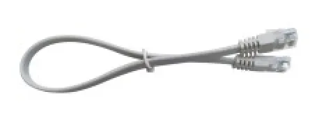 |
Used for connecting two adjacent products |
| 0.8m |  |
Used for connecting products between upper and lower floors |
| 2.6m |  |
Used for connection between main and auxiliary cabinets,controllers, status indication products, and products |
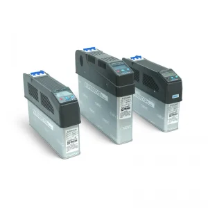
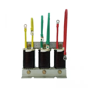
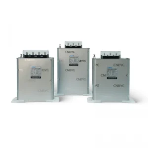
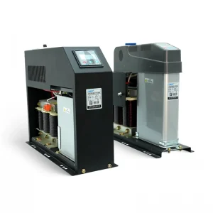
Related Products

Request a Custom Quote
Interested in this product? Fill out the form below and our sales team will get back to you within 24 hours.