Three Phase Series Filter Reactor Application Guide
A three phase series filter reactor protects capacitor banks from harmonic resonance and limits inrush when tuned for specific grid conditions. This guide focuses on practical evaluation steps for U.S. industrial and commercial buyers—measurement, documentation, and lifecycle support—not generic marketing claims. Where equipment selection is involved, cross-check public specifications on cnbygele.com and confirm project-specific limits with your utility or consulting engineer. Section checklists can be reused as RFQ attachments and commissioning handover outlines.
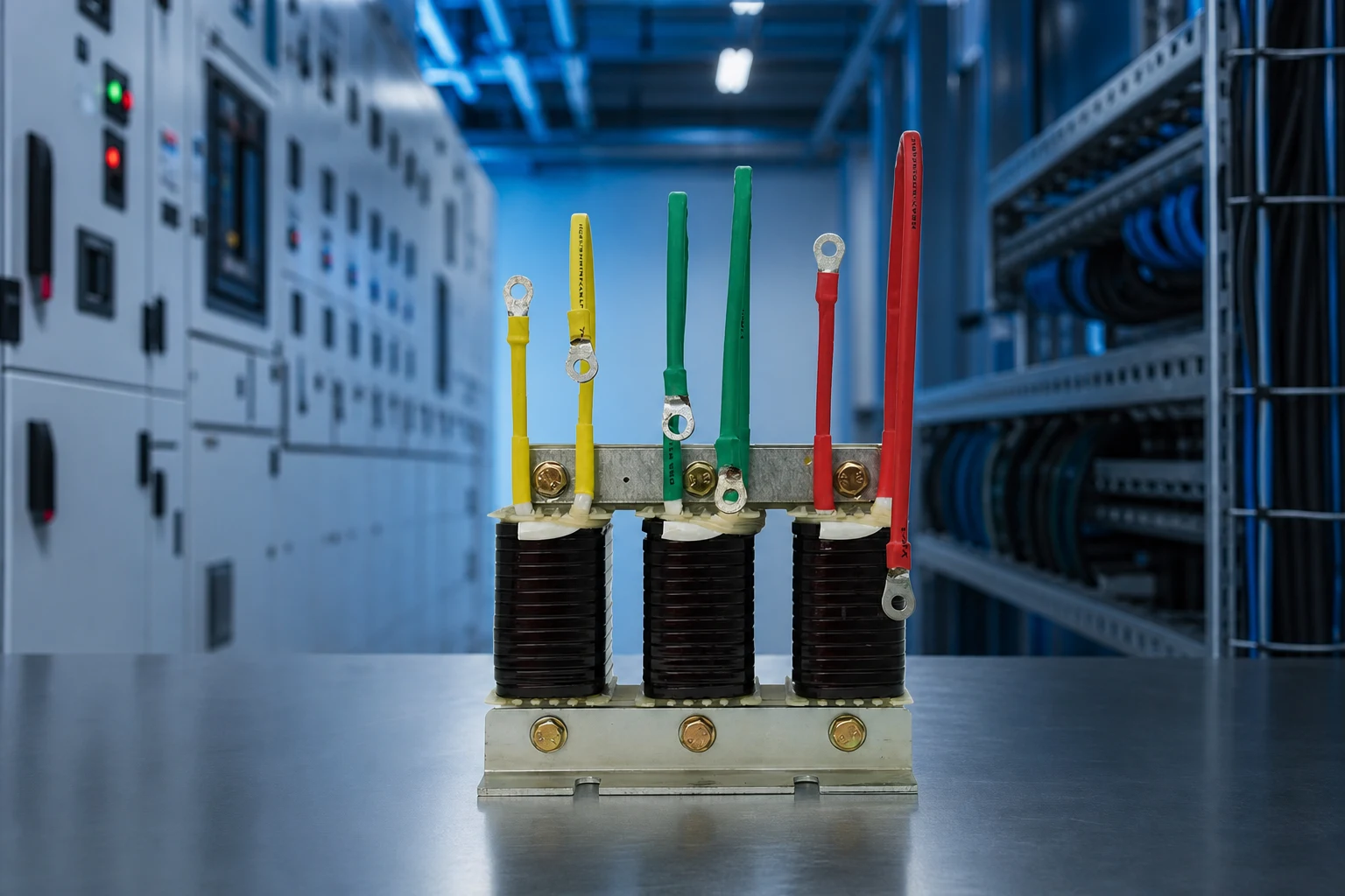
Part 1. Why Series Reactors Are Used
Reactors shift resonant frequency away from dominant harmonics when paired with shunt capacitors.
Power quality projects succeed when measurement, design, and procurement stay aligned across owner, consultant, and panel builder roles.
Document nominal voltage, available fault level, and ambient conditions before final equipment selection.
Use conservative language for performance claims until site-specific studies confirm targets.
Capture nameplate data, single-line drawings, and utility interconnection rules in the RFQ package to reduce back-and-forth during technical review.
If your site mixes linear motors and nonlinear electronics, treat harmonic and reactive targets as linked requirements rather than separate purchases.
Define acceptance criteria before shipment—power factor, step response, or THD at agreed load points—so commissioning disputes are less likely.
Part 2. Sizing and Thermal Duty
Reactor inductance must match bank kvar and system voltage; verify continuous current and harmonic spectrum.
Compare total installed cost including reactors, controllers, enclosures, and commissioning—not equipment list price alone.
Internal links to SVG product line, low-voltage capacitor banks, and active harmonic filters help buyers navigate related product categories on cnbygele.com.
Lead times and MOQ vary by configuration; confirm in quotation for export shipments.
Capture nameplate data, single-line drawings, and utility interconnection rules in the RFQ package to reduce back-and-forth during technical review.
If your site mixes linear motors and nonlinear electronics, treat harmonic and reactive targets as linked requirements rather than separate purchases.
Define acceptance criteria before shipment—power factor, step response, or THD at agreed load points—so commissioning disputes are less likely.
| Detuning | Typical use | Harmonic focus |
|---|---|---|
| p=7% | General industrial | 5th harmonic shift |
| p=14% | Stronger detuning | Higher harmonic environments |
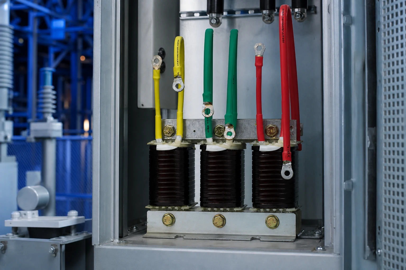
Part 3. Installation Notes
Mount series filter reactors with adequate ventilation and follow torque specs on bus connections.
Post-commissioning, schedule periodic verification of power factor, THD, and temperature rise at key buses.
Keep spare fuses, contactors, or modules identified in the maintenance plan.
Submit project parameters via CNBYG contact for engineering feedback on fit and documentation.
Capture nameplate data, single-line drawings, and utility interconnection rules in the RFQ package to reduce back-and-forth during technical review.
If your site mixes linear motors and nonlinear electronics, treat harmonic and reactive targets as linked requirements rather than separate purchases.
Define acceptance criteria before shipment—power factor, step response, or THD at agreed load points—so commissioning disputes are less likely.
Part 4. Documentation and Handover Checklist
Industrial acceptance should not rely on energization alone—documentation proves ratings, safety, and maintainability for the next maintenance cycle.
Use the tables below as a starting RFQ checklist; your utility or EPC contract may require additional items.
For product-specific datasheets, cross-check related CNBYG product pages and request any missing type test excerpts.
Align factory acceptance tests with items your insurer or utility interconnection agreement may require.
When comparing quotations, normalize currency, Incoterms, and included commissioning services before ranking suppliers.
| Document / item | Purpose | When to request |
|---|---|---|
| Factory type test report | Verify rated voltage, kvar, and temperature rise | Before purchase order |
| Single-line diagram template | Panel layout and protection coordination | Design phase |
| Communication register map | BMS/SCADA integration | Before FAT/SAT |
| Spare parts list (5+ year) | Lifecycle planning | Contract negotiation |
| Commissioning checklist | Acceptance testing | Before energization |
| Project stage | Key action | Owner |
|---|---|---|
| Concept | Define voltage class, load list, and utility rules | Owner / consultant |
| Design | Single-line, protection, and communication | Panel builder / EPC |
| Procurement | Verify ratings, tests, and spares | Buyer / QA |
| Commissioning | Functional tests and as-built docs | Site engineer |
Part 5. Commissioning, Monitoring, and Long-Term Operations
Commissioning should verify that reactive and harmonic targets are met at the point of common coupling, not only at the compensation cabinet terminals.
Functional tests typically include step response, power factor at defined load points, and harmonic readings compared to contract or IEEE 519 guidance where applicable.
Monitoring after energization helps catch hunting, unexpected resonance, or capacitor cell failures before they affect production uptime.
Train maintenance staff on lockout/tagout, discharge timing for capacitors, and which alarms require immediate shutdown versus scheduled service.
Schedule a post-warranty review to reassess load changes—production line upgrades often change compensation needs within three to five years.
Utility account managers can clarify whether PF adjustments affect demand charges only, energy charges, or both—align KPIs before writing acceptance tests.
Keep a spare-parts criticality list (fuses, contactors, fan assemblies, control boards) based on lead time and production impact, not catalog defaults alone.
Recommended CNBYG Products
For project support, explore our related product line, power quality system options, and OEM/ODM capabilities on cnbygele.com.
FAQ
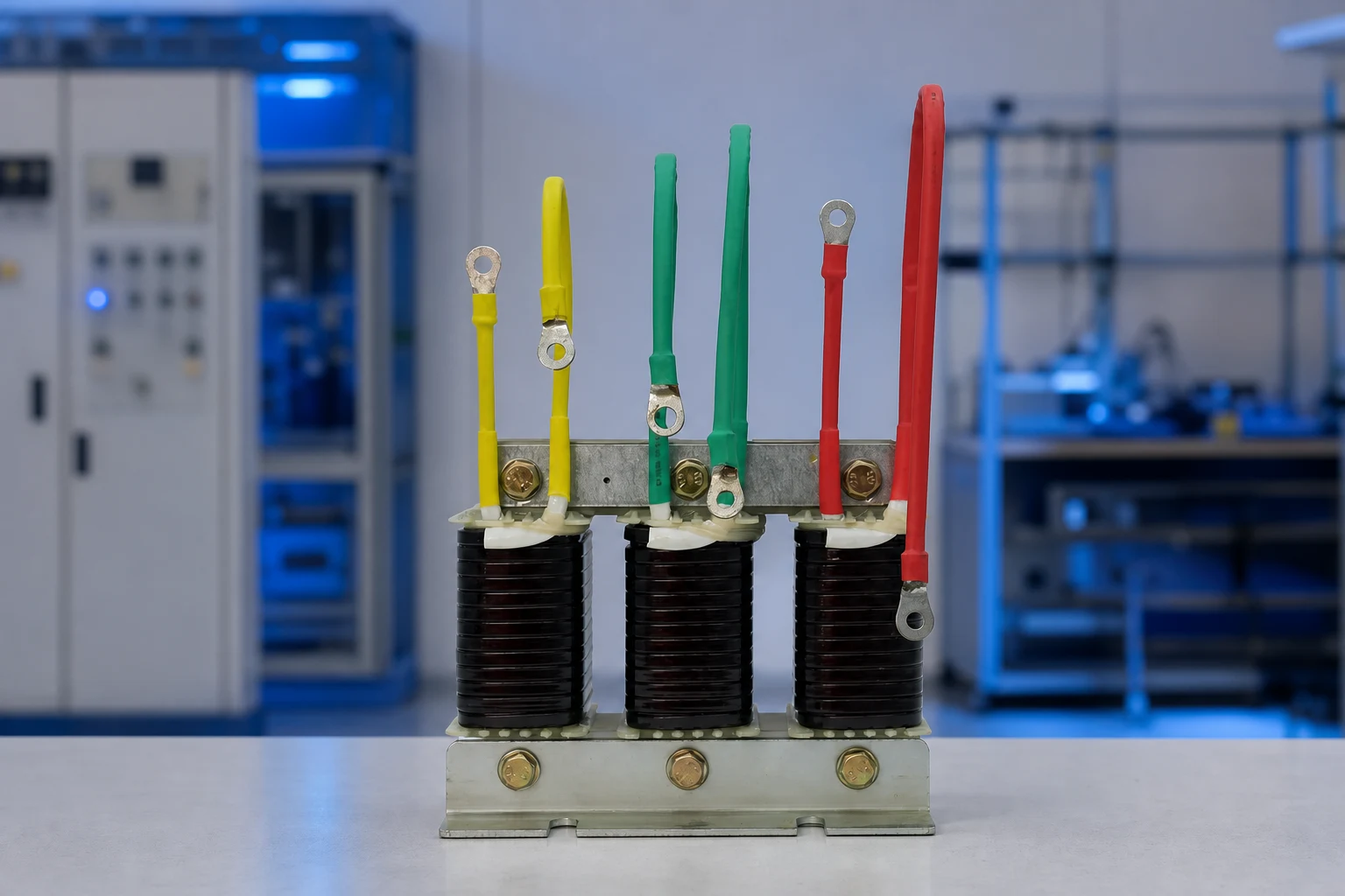
What is a detuned (series filter) reactor and how does it work?
It is a three-phase inductor connected in series with each power factor correction capacitor step, forming a series resonant circuit tuned below the lowest significant harmonic. Below the tuning point the branch is capacitive and corrects power factor; above it the branch is inductive and cannot amplify harmonics.
What detuning factor should I choose?
Common values are 5.67% (~210 Hz), 7% (~189 Hz), and 14% (~134 Hz) on 50 Hz networks. 7% is the general-purpose default for 5th-harmonic-dominant systems; 14% is used where 3rd harmonic is significant; 5.67% gives a tighter margin to the 5th.
What tuning frequency corresponds to a 7% reactor?
About 189 Hz on 50 Hz networks and 227 Hz on 60 Hz networks, comfortably below the 5th harmonic. Always match the tuning to your system frequency.
Why must capacitors be over-rated with a detuned reactor?
The reactor raises the voltage across the capacitor, so capacitors are rated above nominal system voltage. A common relation is Uc = Us / (1 – p), where p is the detuning factor (e.g. 0.07 for 7%).
When should a detuned reactor be added?
Guidance suggests adding detuned reactors when harmonic-producing loads (VFDs, rectifiers, UPS, arc furnaces) exceed roughly 15-20% of the transformer load, or when a plain capacitor bank has failed early.
Does a detuned reactor remove harmonics like an active filter?
Not the same way. A detuned reactor prevents harmonic amplification/resonance and absorbs part of the lower-order harmonic current, but it does not actively cancel harmonics like an APF. Where strict THD limits apply, an active filter may still be needed.
Can I add detuned reactors to an existing capacitor bank?
Only after a harmonic and voltage check, and with capacitors re-rated for the reactor’s voltage rise. Retrofitting reactors onto capacitors not rated for the higher voltage can shorten capacitor life.
References
- CIRCUTOR — Detuned filters working principle
- SpecForge — Reactive Power Compensation (detuning table)
- Gentec — FT100 detuned filter banks (PDF)
- Forte GRIDTUNE — Detuned filter reactor specs
Ready to discuss your project? Contact CNBYG engineering support with your voltage class, load list, and target power factor or THD goals.